
Metallic liner for a fiber wrapped composite pressure vessel for compressed gas storage and transportation

a composite pressure vessel and fiber wrapper technology, applied in the direction of vessel construction details, transportation and packaging, container discharging methods, etc., can solve the problems of high production cost, high production cost, and high cost of process especially for small production volumes

Active Publication Date: 2009-08-13
VINJAMURI INNOVATIONS
View PDF119 Cites 26 Cited by
  • Summary
  • Abstract
  • Description
  • Claims
  • Application Information

AI Technical Summary

Benefits of technology

"The patent describes a metallic liner for a high-pressure gas cylinder made of a seamless metal tube, with top and bottom domes that seamlessly transition into an extended cylindrical neck. The liner also includes seamless top and bottom metal end caps that are attached to the domes. The invention provides a more reliable and durable liner for composite reinforced high-pressure gas cylinders. The manufacturing process involves contouring the ends of the metal tube using a computer numerical control mechanical spinning and forming process, and attaching the end caps to the ends of the tube using various methods such as structural adhesive, shrink fit, threaded connection, a lock nut, or a combination of these. The technical effects of the invention include improved reliability and durability of the metallic liner, as well as simplified manufacturing process."

Problems solved by technology

The flow forming process requires enormous hydraulic pressures and hardened steel mandrel and rollers.
The process tends to be very expensive particularly for smaller production volumes.
Additionally, the metal liner is very thin, essentially used as a fluid permeation barrier and not for any level of load sharing.

Method used


Image

  • Metallic liner for a fiber wrapped composite pressure vessel for compressed gas storage and transportation
  • Metallic liner for a fiber wrapped composite pressure vessel for compressed gas storage and transportation
  • Metallic liner for a fiber wrapped composite pressure vessel for compressed gas storage and transportation

Examples


Embodiment Construction

[0033]In the following description, reference is made to the accompanying drawings, which form a part hereof and which illustrate several embodiments of the present invention. The drawings and the preferred embodiments of the invention are presented with the understanding that the present invention is susceptible of embodiments in many different forms and, therefore, other embodiments may be utilized and structural and operational changes may be made without departing from the scope of the present invention.

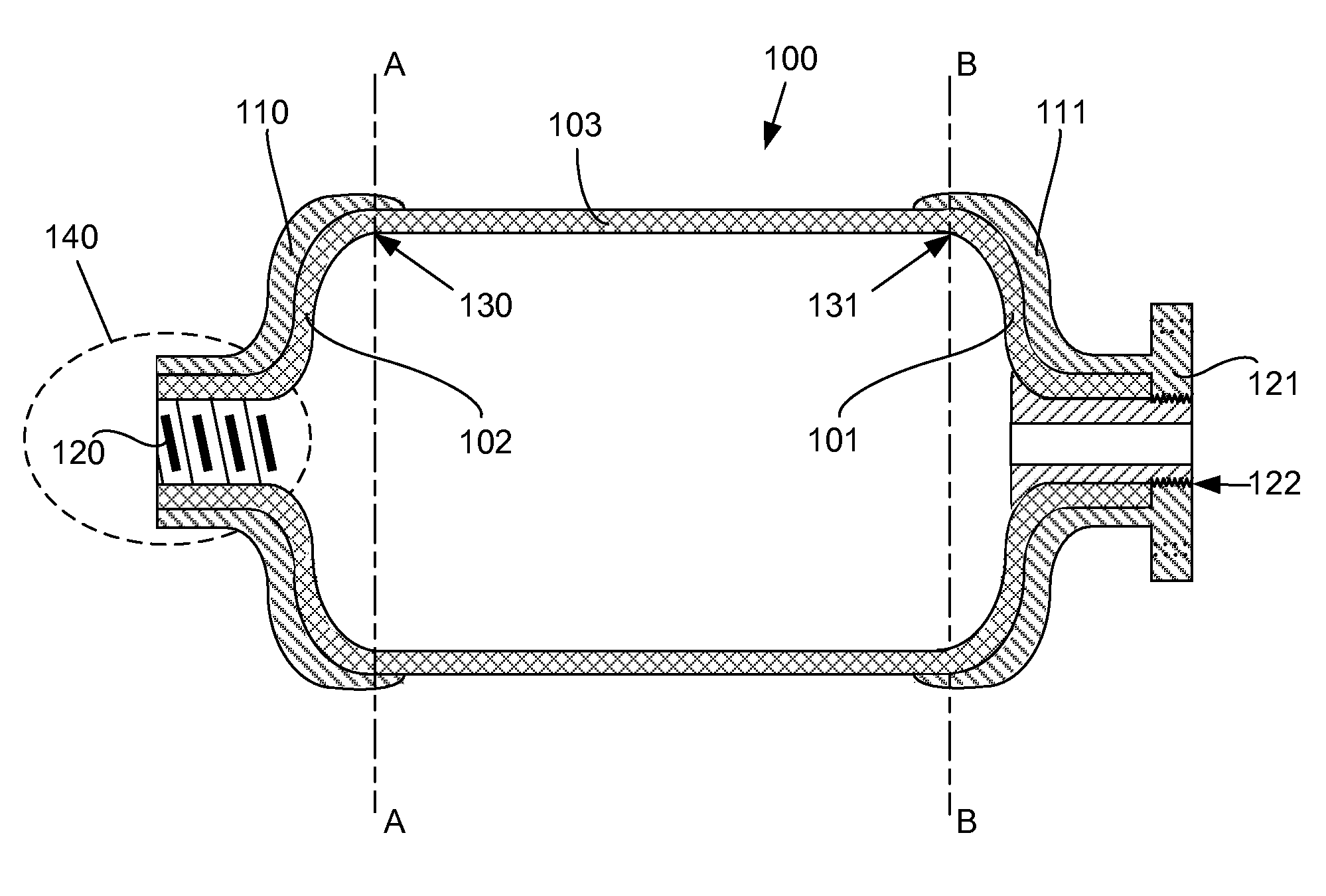
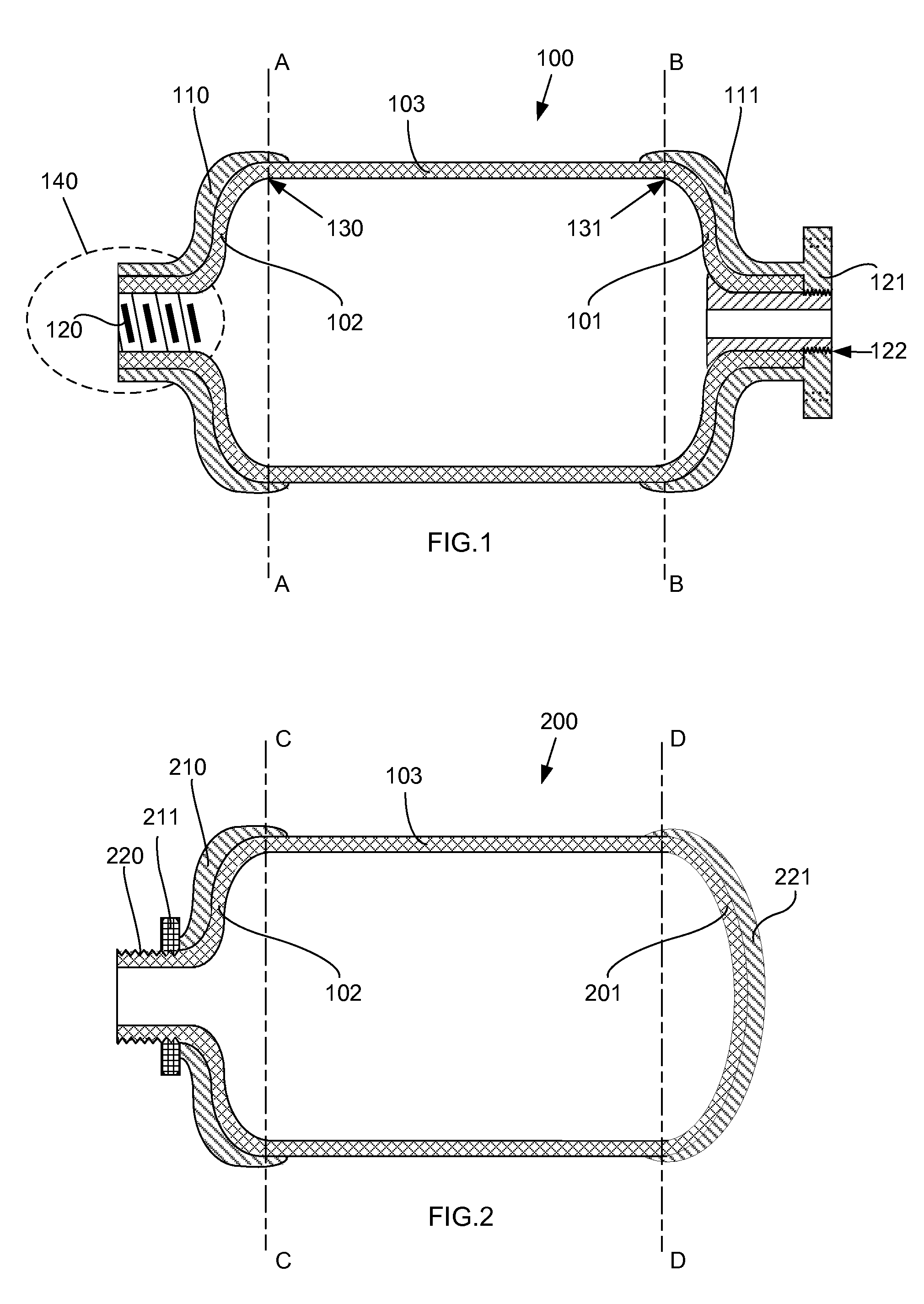
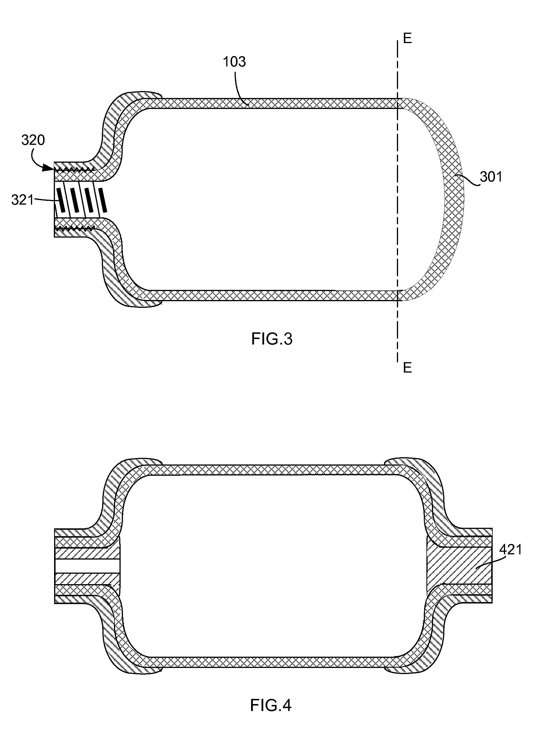
[0034]FIG. 1 shows a sectional side view of a preferred embodiment of the liner (100) for a composite cylinder for high-pressure gas storage and transportation. A liner preferable includes three elements: a metal tube, a top metal end cap and a bottom metal end cap.

[0035]The first element of this embodiment is a metal tube of uniform thickness and uniform diameter. The metal tube comprises three portions: a sidewall (103), a top end (102) to the left of the line A-A, and a bottom...


PUM

PropertyMeasurementUnit
pressureaaaaaaaaaa
thicknessaaaaaaaaaa
shapeaaaaaaaaaa

Abstract

A metallic liner for a composite reinforced high pressure gas cylinder is composed of a seamless metal tube contoured with a top dome and bottom dome. The liner is further composed of a seamless top metal end cap having a mating shape of the top dome and a seamless bottom metal end cap having a mating shape of the bottom dome. Alternatively, an extruded cup is shaped to a dome at the open end and one or two seamless metal end caps are used. In the method of manufacturing, the top and bottom ends of the metal tube are contoured, the end caps are produced, and one or two end caps are attached to the ends of the tube.

Description

FIELD OF INVENTION[0001]In the field of high-pressure gas tanks used for the storage and transportation of compressed gases, a seamless metal liner, and method of making the liner, is disclosed for use in a fiber-wrapped composite cylinder wherein the liner includes an end cap attached to a dome end to strengthen the liner.BACKGROUND OF THE INVENTION[0002]A fiber-wrapped composite gas cylinder for high-pressures, also known as a filament-wound pressure vessel, essentially consists of two components: a cylindrical or spherical containment shell or liner (hereinafter primarily referred to as a “liner”) and a structural composite material. The composite is a continuously wrapped fiber-resin matrix material. The liner, over which the composite is wrapped and cured in place, provides means for preventing or minimizing gas permeation through the composite. In addition, in composite cylinders with a metallic liner, the liner provides a means for load sharing with the composite.[0003]Machin...

Claims


Application Information

Patent Timeline
Patent Type & Authority Applications(United States)
IPC IPC(8): F17C1/06
CPCF17C1/02F17C2270/079F17C13/06F17C2201/0109F17C2203/012F17C2201/054F17C2201/056F17C2201/058F17C2203/0658F17C2203/0604F17C2203/0619F17C2203/0643F17C2203/0646F17C2203/0648F17C2203/066F17C2203/0663F17C2205/0126F17C2205/0138F17C2205/0305F17C2209/234F17C2205/0323F17C2205/0338F17C2205/0397F17C2209/224F17C2209/227F17C2221/012F17C2221/031F17C2221/033F17C2223/0123Y02E60/321F17C2223/036F17C2260/012F17C2260/042F17C2270/0168F17C2270/0186F17C2270/0194F17C2270/0197F17C1/06Y02E60/32
Inventor VINJAMURI, GOPALA KRISHNA
Owner VINJAMURI INNOVATIONS
Learn More