
Transmission Gearbox Family in Parallel Shaft Transmission System

a transmission gearbox and gearbox technology, applied in mechanical equipment, transportation and packaging, gearboxes, etc., can solve the problems of multi-speed transmissions, reduce the efficiency of torque converters, and low mechanical efficiency, so as to reduce the slippery speed of relative clutches, increase the durability of transmissions, and minimize heat

Inactive Publication Date: 2009-08-13
YANG CHING MIN +3
View PDF0 Cites 16 Cited by
  • Summary
  • Abstract
  • Description
  • Claims
  • Application Information

AI Technical Summary

Benefits of technology

[0012]One of the objectives of the present invention is to introduce a new transmission family by using the gearwheels as minimum numbers as possible to achieve the full range of the gear ratios which overcomes the disadvantages in automatic transmissions, automated manual transmissions (AMT) and dual-clutch transmissions (DCT) which typically require more gearwheels. The virtue of this invention is to obtain each selected gear ratio by interconnecting multiple gearwheels and or multiple gear sets simultaneously instead of using one gear set for only one selected gear ratio. Therefore, the total number of gearwheels is reduced to a minimum level, the size of the gearbox is designed to a compact level and the bending moment is limited in a negligible level in such parallel shaft transmission system. Another objective of the present invention is to reduce the relative clutch slippery speed between driving and driven clutch pads and to increase the durability of the transmission by minimizing the heat in the transmission gearboxes that are equipped with hydraulic clutches. Meanwhile, the cost effective material for the clutch pad can be used without compromising the basic cooling requirement and the longevity of the gearbox.
[0013]In one aspect of the present invention, the transmission gearbox comprises three parallel shafts and multiple external gear sets. Each of the external gear sets consists of external gearwheels which are selectively interconnected to each of the mentioned three parallel shafts for the forward driving speeds. In another aspect of the present invention, the external gear sets contain the continuously interconnected gearwheels which reduce the center distance between the parallel shafts whenever it becomes necessary.
[0015]In still yet another aspect of the present invention, in the five-speed transmission gearboxes, six of eight gearwheels are used for more than one forward speed ratio. In yet a further aspect of the present invention, in the six-speed transmission gearboxes with ten forward driving gearwheels, nine of ten gearwheels are used for more than one forward speed ratio. In yet a further aspect of the present invention, in the six-speed transmission gearboxes with eleven forward driving gearwheels, ten of eleven gearwheels are used for more than one forward speed ratio. In yet a further aspect of the present invention, in the six-speed transmission gearboxes with nine forward driving gearwheels, nine of nine gearwheels are used for more than one forward speed ratio. In yet a further aspect of the present invention, in seven-speed, eight-speed and nine-speed transmission gearboxes, nine of nine gearwheels are used for more than one forward speed ratio. These features give the maximum reduction of the total number of gearwheels.
[0016]The present invention is embodied in a family of transmission gearboxes that utilize the minimum numbers of forward driving gearwheels to obtain the multiple gear speed ratios in the selected five, six, seven, eight and nine speed gear ratios, which provide a significantly low cost for massive production. In further description, five forward speeds are achieved by selectively interconnecting a minimum of the eight forward speed gearwheels of the five-speed transmission gearboxes; herewith, six forward speeds are achieved by selectively interconnecting a minimum of nine forward speed gearwheels of the six-speed transmission gearboxes; herewith, seven forward speeds are achieved by selectively interconnecting a minimum of nine forward speed gearwheels of the seven-speed transmission gearboxes; herewith, eight forward speeds are achieved by selectively interconnecting a minimum of nine forward speed gearwheels of the eight-speed transmission gearboxes and herewith, nine forward speeds are also achieved by selectively interconnecting a minimum of nine forward speed gearwheels of the transmission gearboxes.
[0017]Another embodiment of the present invention is to provide a new type of direct clutch-to-clutch transmission gearboxes, which is operated at a lower clutch slippery speed with more reliable and lower heat generation than a dual-clutch transmission gearbox.

Problems solved by technology

Such multi-speed transmissions still use the conventional torque converter for comfort shifting, but have quite low mechanical efficiency.
The inherent slip reduces the efficiency of the torque converter.
Although lock-up device is usually equipped in newly developed transmissions, only a few gears can be locked up to avoid energy loss and the lock-up usually is not complete because partial slippery still exists to prevent the noise and vibration.
Therefore, its overall efficiency is still low as long as the torque converter is used and the torque converter is considered as a big technical barrier to efficiency improvement.
However, the clutch assembly working within the dual-clutch transmission generates a considerable amount of heat (U.S. Pat. No. 6,715,597).
These conventional automatic transmissions, either using planetary gear sets or parallel shafts with external gear sets, usually have an uncontrolled way to dissipate the heat that is generated from torque converter, clutches, gears and actuators, etc., by using a transmission fluid cooler.
However, in the dual-clutch transmission, since more heat can be generated in a short period of time, this cooling method is insufficient to maintain the required fluid temperature.
The requirements to the materials in friction elements are, hence, higher, and the way to cool down the transmission fluid and its control procedures are much more complicated (U.S. Pat. No. 6,715,597).
Although dual-clutch transmission provides high mechanical efficiency and shifting quality, it can only be used in limited types of lighter duty vehicles due to these disadvantages.
However, the drawbacks of this technique are the need to install additional damper in the large diameter gearwheel and the introduction of bending moment to engine crankshaft (U.S. Pat. No. 7,305,900).

Method used


Image

  • Transmission Gearbox Family in Parallel Shaft Transmission System
  • Transmission Gearbox Family in Parallel Shaft Transmission System
  • Transmission Gearbox Family in Parallel Shaft Transmission System

Examples


Embodiment Construction

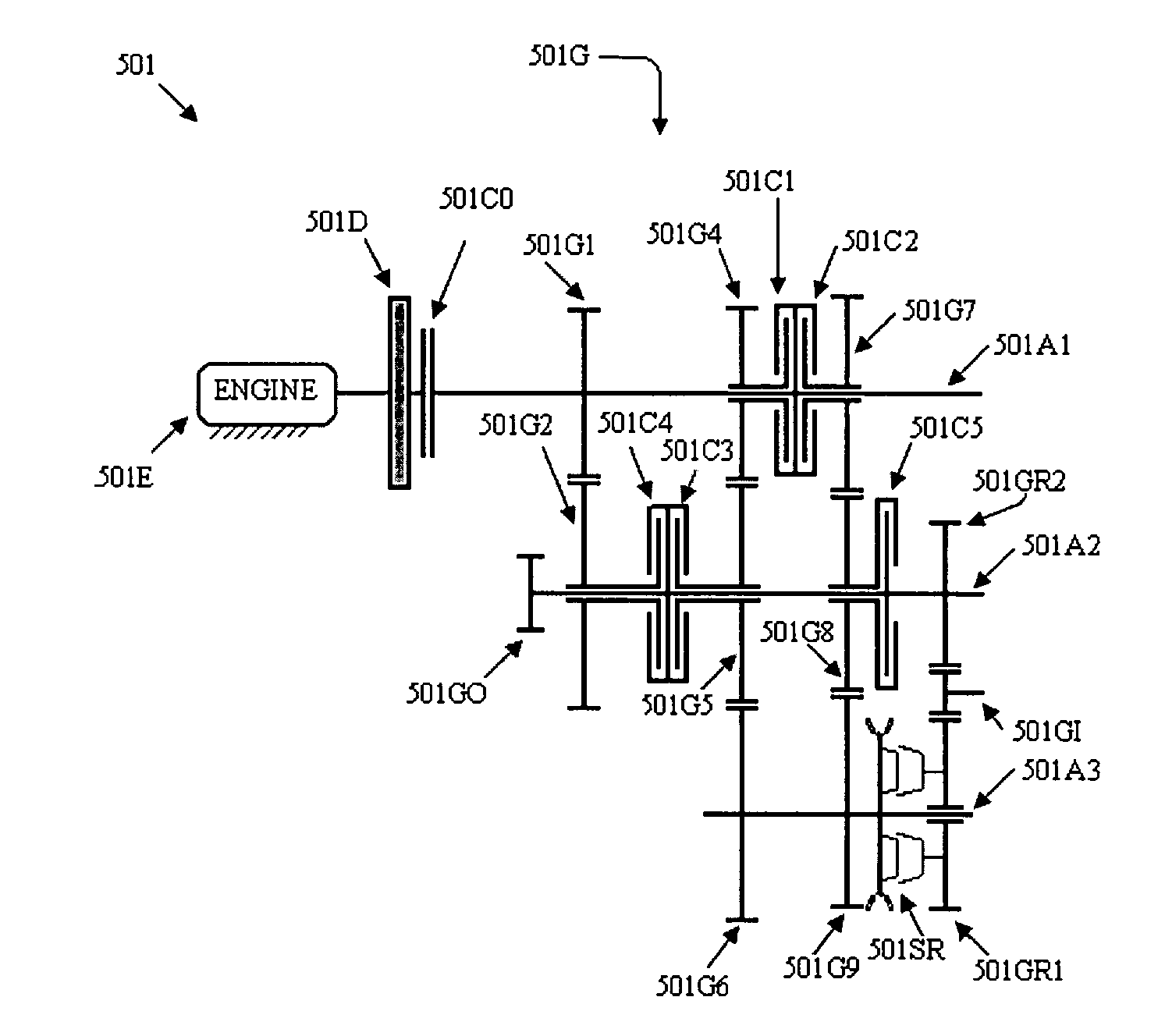
[0064]A powertrain system 501, shown in FIG. 1, has a conventional engine 501E and a five-speed transmission gearbox 501G.

[0065]The five-speed transmission gearbox 501G includes a mechanical damper 501D, a main clutch 501C0, an input shaft 501A1, an output shaft 501A2 which has a fixed output gearwheel 501GO to transmit torque to a final drive(not shown) and an intermediate shaft 501A3. 501A1 is selectively interconnected with 501C0. 501G also includes a plurality of forward driving gearwheels 501G1, which is fixed on 501A1, 501G2, 501G4, 501G5, 501G6, 501G7, 501G8 and 501G9 which are free to rotate and selectively interconnected with input shaft 501A1, the output shaft 501A2 and the intermediate shaft 501A3 by clutches 501C1, 501C2, 501C3, 501C4 and 501C5, and a synchronizer 501S1, respectively. 501G6 and 501G9 are linked with each other on the intermediate shaft 501A3. 501G also has a reverse driving gearwheel 501GR1 which is free to rotate and selectively interconnected with the ...


PUM


Abstract

This invention relates to a transmission gearbox family to provide five, six, seven, eight and nine speed ratios with a reverse speed ratio and a neutral condition in motor vehicles. The invention arranges a plurality of gearwheels in parallel shaft systems such that minimum number of gearwheels is obtained by either combination of clutches with synchronizers for transmission gearboxes with a torque converter and direct clutch to clutch gearboxes without a torque converter, or synchronizers for automated manual transmission gearboxes. For total number of the gearwheels involving in forward driving, five-speed transmission gearboxes have eight gearwheels, six-speed transmission gearboxes have minimum of nine gearwheels, seven-speed transmission gearboxes have minimum of nine gearwheels, eight-speed transmission gearboxes have minimum of nine gearwheels and nine-speed transmission gearboxes have minimum of nine gearwheels, respectively. Each family member has three parallel shafts with either selectively or continuously interconnected with the gearwheels through the engaged single or multiple torque transmitting mechanisms. The direct clutch-to-clutch gearboxes without a torque converter and automated manual gearboxes have a mechanical damper and a main clutch.

Description

CROSS-REFERENCE TO RELATED APPLICATIONS[0001]7,305,900Dec. 10, 2007Suzuki, et al.7,294,091Nov. 13, 2007Yasui, et al.7,082,850Aug. 1, 2006Hughes, et al.6,715,597Apr. 6, 2004Buchanan, et al.6,705,967Mar. 16, 2004Raghavan, et al.6,656,078Dec. 2, 2003Raghavan, et al.6,463,821Oct. 15, 2002Reed, Jr., et al.5,950,781Sep. 14, 1999Adamis, et al.5,106,352Apr. 21, 1992LepelletierSTATEMENT REGARDING FEDERALLY SPONSORED RESEARCH OR DEVELOPMENT[0002]Not ApplicableTHE NAMES OF THE PARTIES TO A JOINT RESEARCH AGREEMENT[0003]Not ApplicableINCORPORATION-BY-REFERENCE OF MATERIAL SUBMITTED ON A COMPACT DISC[0004]Not ApplicableBACKGROUND OF THE INVENTION[0005]A powertrain system used in a passenger vehicle is comprised of an engine, multi-speed transmission and a differential or final drive system. The premier function of transmission is to extend the operating range of the vehicle by allowing the engine to perform in the torque range several times higher than the engine torque as the transmission ratio...

Claims


Application Information

Patent Timeline
Patent Type & Authority Applications(United States)
IPC IPC(8): F16H3/08F16H3/093
CPCF16H3/093F16H2003/0807F16H2003/0933F16H2003/0938F16H2200/0047Y10T74/19242F16H2200/0056F16H2200/006F16H2200/0065Y10T74/19233F16H2200/0052
Inventor YANG, CHING-MINLU, JIAN-GANGWANG, DAMINGSHI, GUOJUN
Owner YANG CHING MIN
Learn More