
Erase count recovery

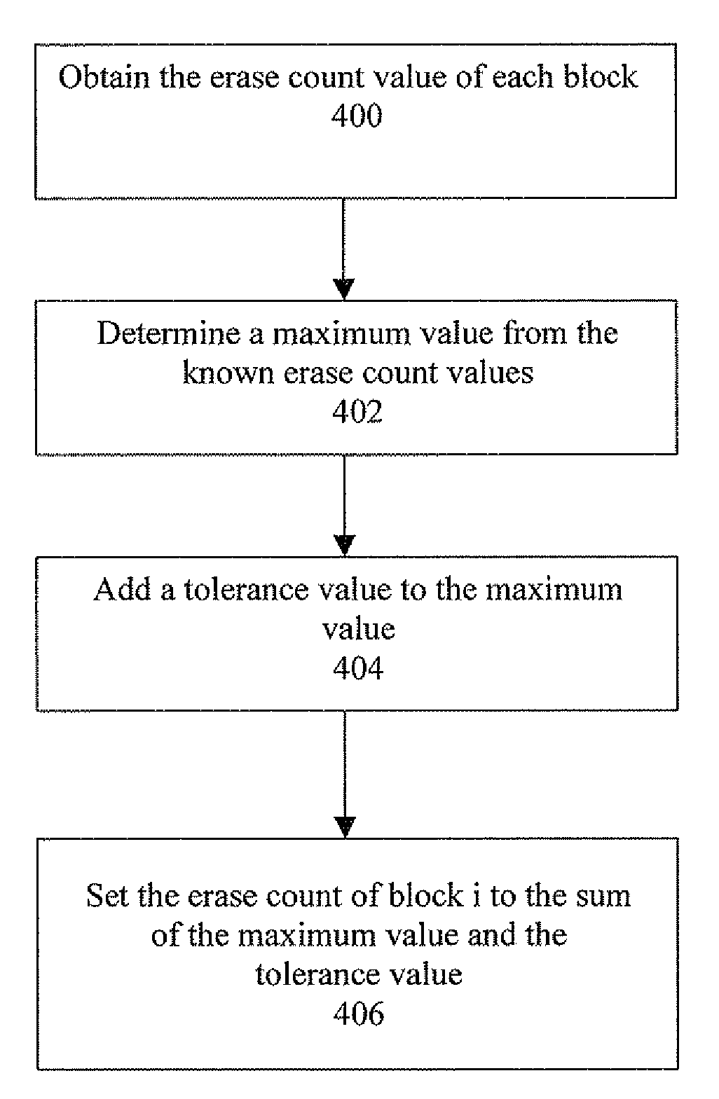
a technology of erase count and recovery method, applied in the field of erase count recovery, can solve the problems of loss or invalidation of erase count, too many “bad” blocks, and find a mismatch

Inactive Publication Date: 2009-08-06
SANDISK IL
View PDF24 Cites 23 Cited by
  • Summary
  • Abstract
  • Description
  • Claims
  • Application Information

AI Technical Summary

Problems solved by technology

This count is important, as too many erase operations performed on a given block lead to wear.
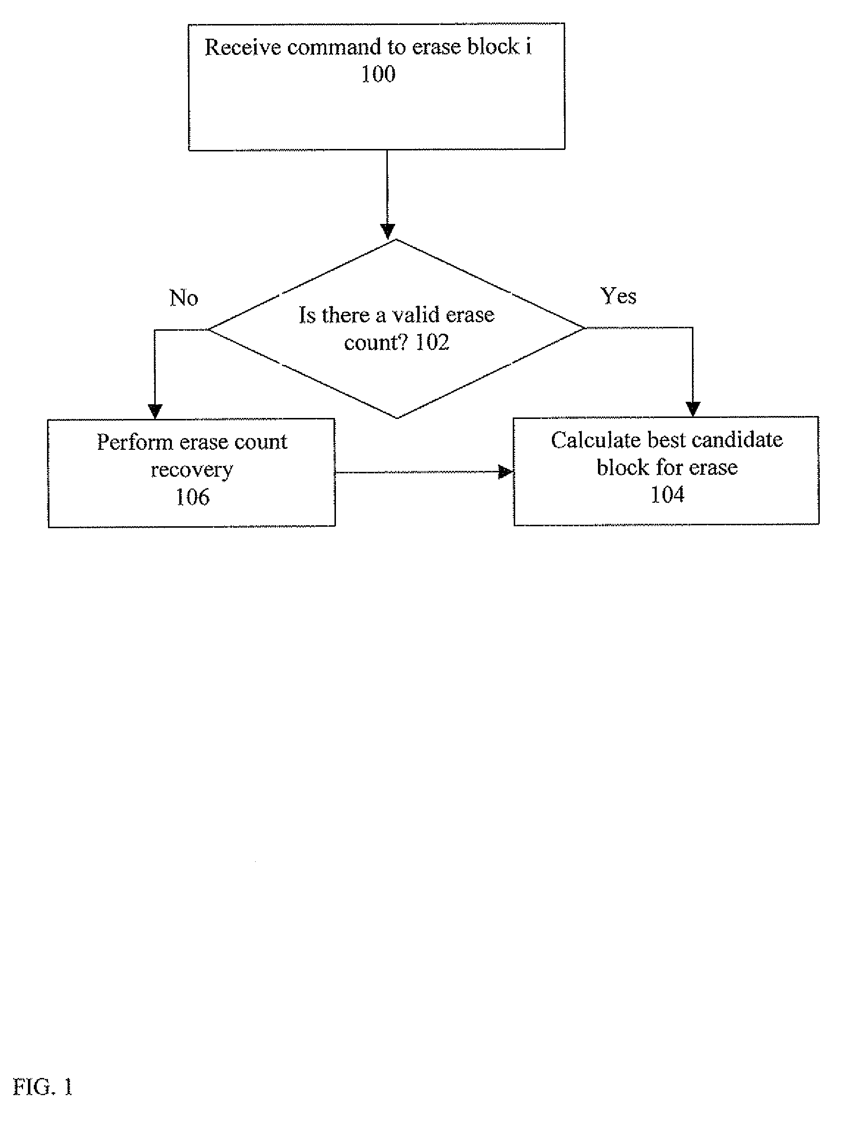
A power failure may cause the loss or invalidation of the erase count at any stage of this updating process, since during the process the flash manager is typically using and relying on an intermediate erase count stored in a volatile memory.
1. When the flash manager (using a flash management algorithm) needs to erase a block, it reads the erase count of the block to be erased from the flash media and copies it to a volatile memory (RAM or DRAM). The flash manager then erases the block, the erase count is incremented and the erase count checksum is calculated by the flash manager (which stores the erase count and the erase count checksum in the volatile memory). The flash manager then aims to write the updated erase count and the checksum into the erased block. During this time, i.e., prior to writing or during writing, if there is a power failure, the erase count and / or the checksum may be only partially written. When the flash manager reads the block erase count and tries to verify it with the checksum, it will find a mismatch.
2. Another scenario is that at least one of the erase count bits has been flipped due to the fact that the flash manager has not refreshed the block. When a block is not erased for a period of time specified by the flash manufacturer, the block's bits are flipped. Consequently, it is required that in every such period of time, every block needs to be erased in order to avoid the situation of bit flips. When such a block (that stores data and has not been erased for some time) is read by the flash algorithm and its erase count parameter bits have been flipped, the erase count will not match the checksum that is also stored in the flash. In this case the flash algorithm may consider the erase count as invalid. Another situation of invalid erase count is when the bits of the checksum have been flipped. In this case the erase count will not match the checksum and thus the erase count will be considered an invalid erase count.
Both of these approaches have disadvantages, the first quickly leading to too many “bad” blocks, and the second being too risky.

Method used


Image

  • Erase count recovery
  • Erase count recovery
  • Erase count recovery

Examples


Embodiment Construction

[0024]According to an example embodiment, a flash manager using a flash management algorithm obtains a new erase count for a block for which the erase count was lost, using known erase counts of other blocks of the flash memory, and assigns the new erase count to the block. In some embodiments, the flash management algorithm performs wear leveling (and is also referred to as a wear leveling algorithm) and the known erase counts may be obtained from wear leveling information. The flash management algorithm may be executed on the flash memory device processor / controller or on another device (which is not a flash device). The other device may be, e.g., a host side flash controller, a host side volatile memory (“VM”, exemplarily a RAM or DRAM) or a network server to which the flash device is operationally connected. The flash management algorithm typically uses a volatile memory to store an intermediate erase count. This volatile memory may but need not be located independently of the f...


PUM


Abstract

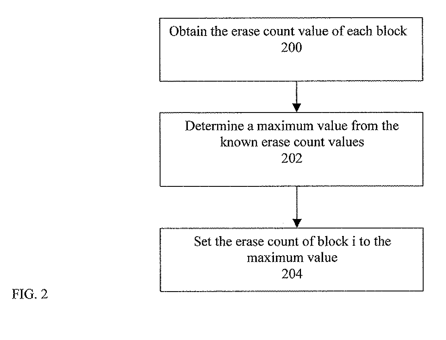
An erase count of a flash memory block which is lost, e.g., due to power failure is updated or replaced by using known erase counts of other blocks of the flash memory. A flash management algorithm assigns a new erase count value instead of the lost one based on either a maximum value, an average value or a value combining the maximum value of the known erase counts and some tolerance value. The known values may be obtained from wear leveling data or from a stored erase history.

Description

FIELD OF THE INVENTION[0001]The invention relates in general to data storage devices and methods for an Erase operation in flash memories, and more particularly to methods of updating a lost or invalid erase count of a given block of a flash memory.BACKGROUND OF THE INVENTION[0002]Flash memory devices (or simply “flash devices”) are well known in the art. Such devices may be used by a host system for storing data in flash media, which may be of NOR or NAND type. The operation of flash memory devices is typically controlled (managed) by a microprocessor-based controller with the help of a non volatile random access memory such as ROM / NOR and, in some cases, of a volatile random access memory such as RAM, DRAM or PSRAM. The flash device and the host system communicate via a communication port in the flash device. The components of the flash device are typically housed together in a common housing.[0003]The controller may perform read operations, write operations and erase operations o...

Claims


Application Information

Patent Timeline
IPC IPC(8): G06F12/02
CPCG06F2212/7211G06F12/0246
Inventor MOSEK, AMIR
Owner SANDISK IL
Learn More