Probe straightness measuring method

a technology of straightness measurement and probe, which is applied in the direction of mechanical measuring arrangements, instruments, and mechanical means, can solve the problems of inability to provide accurate straightness measurement, high economic burden on electrical capacitor sensors, and attachment/detachment work, so as to facilitate processing and assembling work, the effect of deteriorating the measurement accuracy

Active Publication Date: 2009-08-06
MITUTOYO CORP
View PDF4 Cites 10 Cited by
  • Summary
  • Abstract
  • Description
  • Claims
  • Application Information

AI Technical Summary

Benefits of technology

[0028]Accordingly, the deterioration of the measurement accuracy caused on account of a linear guide mechanism of the probe and the like that surfaces when the scanning measurement is conducted while driving the measurement-piece moving mechanism can be avoided. Thus, since it is not required to assemble and process the linear guide mechanism with high accuracy or to assemble the scanning probe with high attachment accuracy, the processing and assembling work can be facilitated and the burden on the workers can be reduced.

Problems solved by technology

Such a separate electro-capacitance sensor accompanies a great economic burden and attachment / detachment work.
Furthermore, since a bending force of a cable that connects the electro-capacitance sensor and a controller is applied as an external force on the linear guide mechanism for moving the spindle, the spindle depicts a movement locus different from that depicted without the electro-capacitance sensor being attached (i.e. with the stylus being attached), thus failing to provide an accurate straightness measurement.

Method used


Image

  • Probe straightness measuring method
  • Probe straightness measuring method
  • Probe straightness measuring method

Examples


embodiment

Advantage of Embodiment

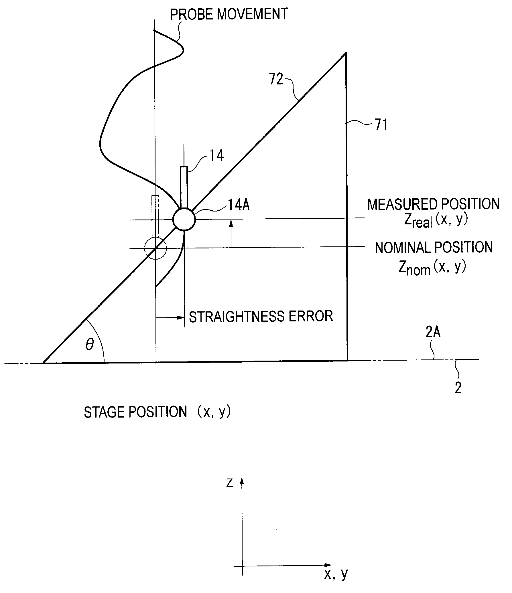
[0067]According to the above embodiment, the straightness of the probe can be measured in an actual use environment without requiring a separate straightness-measuring sensor. Thus, economic burden can be reduced. In addition, attachment and detachment work of a straightness-measuring sensor is not required, so that efficiency of measurement process can be improved. Further, the accuracy of the straightness is not influenced by the accuracy of the electrostatic capacity sensor. Furthermore, since the bending force of a cable that connects an electro-capacitance sensor to a controller is not applied to the measurement piece as an external force, highly accurate measurement can be achieved.

[0068]The straightness errors obtained through a straightness measuring process are stored in the straightness correction data storage 33 and the correction values corresponding to the detected values of the sensor displacement detector 18 are read from the straightness correc...


PUM


Abstract

A probe straightness measuring method includes: placing a measurement jig having a measurement reference surface with a known profile error on a stage surface of an XY stage so that the measurement reference surface is slanted in a moving direction of the XY stage; measuring a displaced position of the measurement piece by a displacement detector of the probe each time the XY stage is moved for a predetermined distance while controlling a driving actuator so that the measurement piece of a probe touches the measurement reference surface at a constant pressure; and calculating a straightness error of a measurement-piece moving mechanism on a basis of a measured position of the measurement piece obtained in the measuring, a nominal position of the measurement piece obtained by a calculation and a slant angle of the measurement reference surface.

Description

BACKGROUND OF THE INVENTION[0001]1. Field of the Invention[0002]The present invention relates to a method for measuring a straightness of a probe. More specifically, the invention relates to a method for measuring a straightness of a probe of a surface texture measuring instrument that measures a surface texture such as a profile and surface roughness of an object to be measured using the probe.[0003]2. Description of Related Art[0004]Roughness measuring instruments, profile measuring instruments, scanning coordinate measuring instruments and the like are known as surface texture measuring instruments for measuring a surface texture such as a profile and surface roughness of an object to be measured using a probe.[0005]For instance, a scanning coordinate measuring instrument includes a Z-axis slider that is capable of vertical (i.e. Z-axis direction) movement and a probe attached to the Z-axis slider, the probe having a stylus (measurement piece) that is capable of minute displaceme...

Claims


Application Information

Patent Timeline
Patent Type & Authority Applications(United States)
IPC IPC(8): G01B21/00G06F15/00
CPCG01B3/008G01B21/042G01B5/012
Inventor NEMOTO, KENTAROYAMAGATA, MASAOKI
Owner MITUTOYO CORP
Why Eureka
Try Eureka