
Tire tread discharge grooves with textured bases

Inactive Publication Date: 2009-08-06
BONKO MARK LEONARD +2
View PDF38 Cites 25 Cited by
  • Summary
  • Abstract
  • Description
  • Claims
  • Application Information

AI Technical Summary

Benefits of technology

[0004]The present invention is directed to a pneumatic tire comprising an axis of rotation and a tread. The tread has a plurality of traction elements and a discharge groove. The discharge groove has a base interposed between radially extending sides formed by side walls of the traction elements. The base of the discharge groove defines a matrix of circumferentially extending rectangular ramp structures. One ramp structure of the matrix extends circumferentially, from a radially inner first end portion, in a direction of rotation of the tire and radially outward to a radially outer second end portion. The radially outer second end portion defines an edge portion extending parallel to the axis of rotation of the tire. The edge portion improves traction of the tire and evacuation of the discharge groove.
[0007]In another aspect of the disclosed invention, a second ramp structure of the matrix extends circumferentially, from a radially outer first end portion, in a direction of rotation of the tire and radially inward to a radially inner second end portion. The radially outer first end portion defines a second edge portion extending parallel to the axis of rotation of the tire. The second edge portion improves traction of the tire and evacuation of the discharge groove.
[0025]“Chafers” refers to narrow strips of material placed around the outside of the bead to protect cord plies from the rim, distribute flexing above the rim, and to seal the tire.

Problems solved by technology

Traction in snow, however, has greatly been sacrificed at the expense of such a look.
The widely spaced lugs of such tires increase the possibility of snow buildup between the lugs during use in areas with snow or other materials.
Such buildup decreases the traction performance under these circumstances.

Method used


Image

  • Tire tread discharge grooves with textured bases
  • Tire tread discharge grooves with textured bases
  • Tire tread discharge grooves with textured bases

Examples


Embodiment Construction

[0066]The following language is of the best presently contemplated mode or modes of carrying out an example embodiment of the invention. This description is made for the purpose of illustrating the general principals of the invention and should not be taken in a limiting sense. The scope of the invention is best determined by reference to the appended claims.

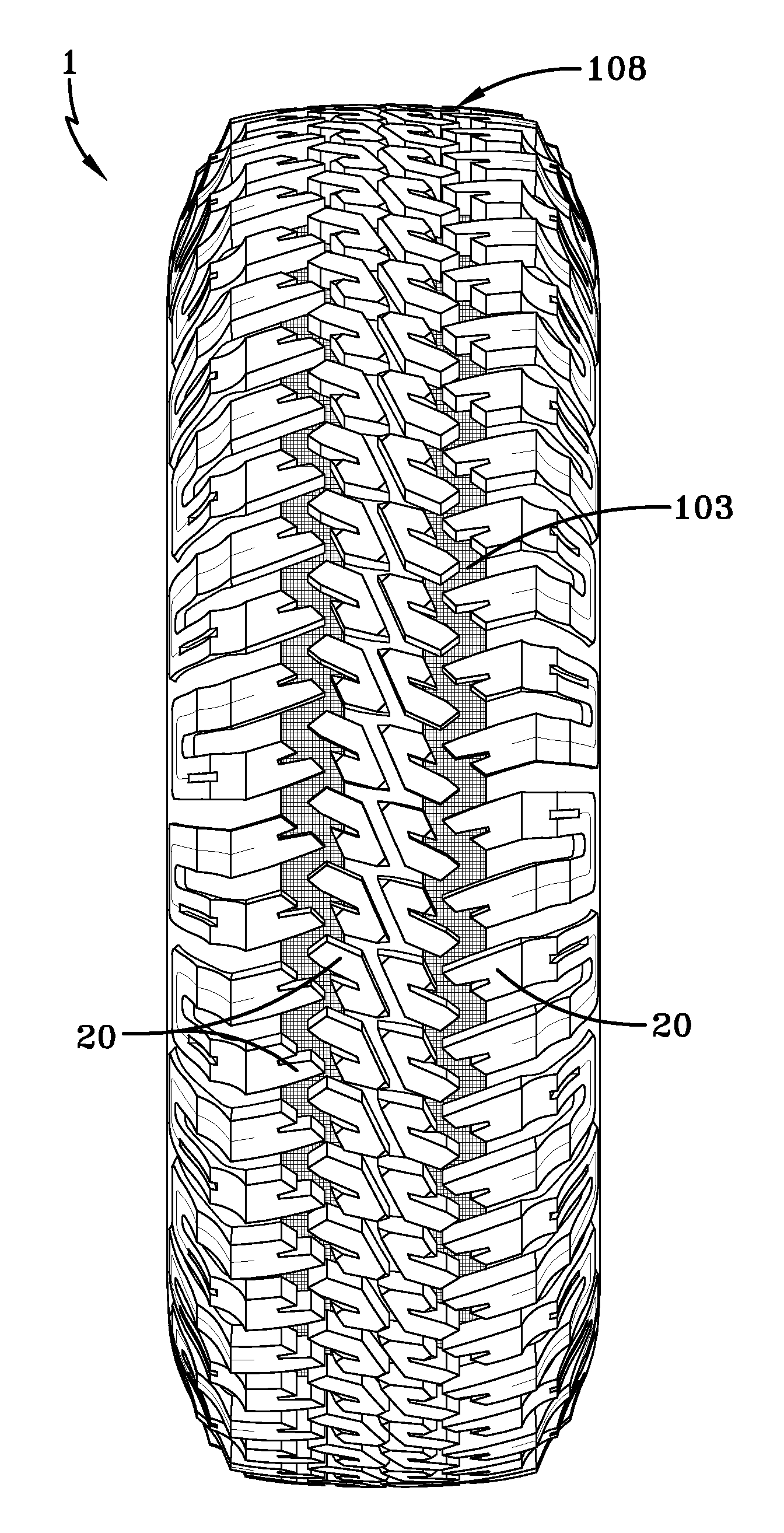
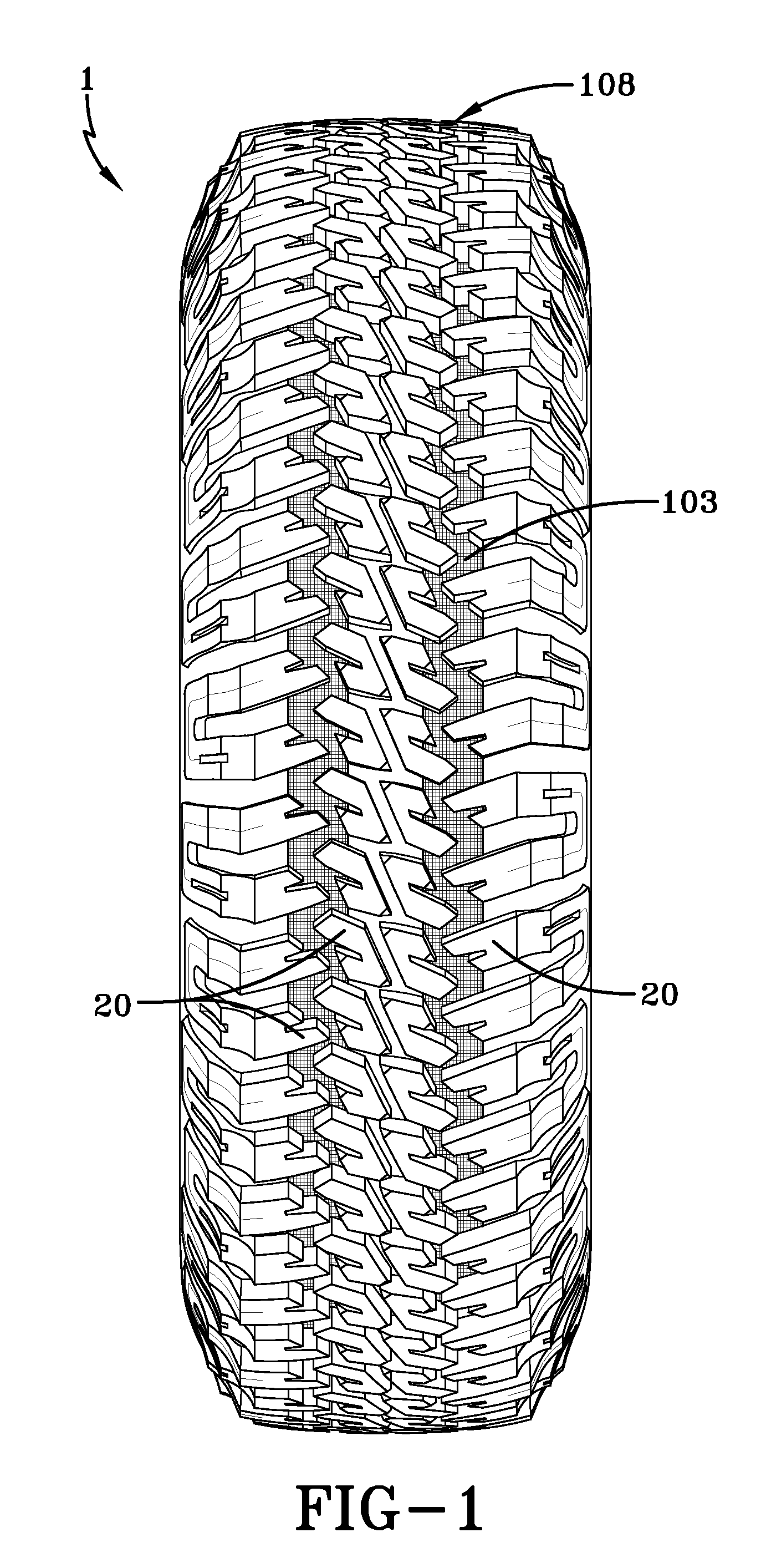
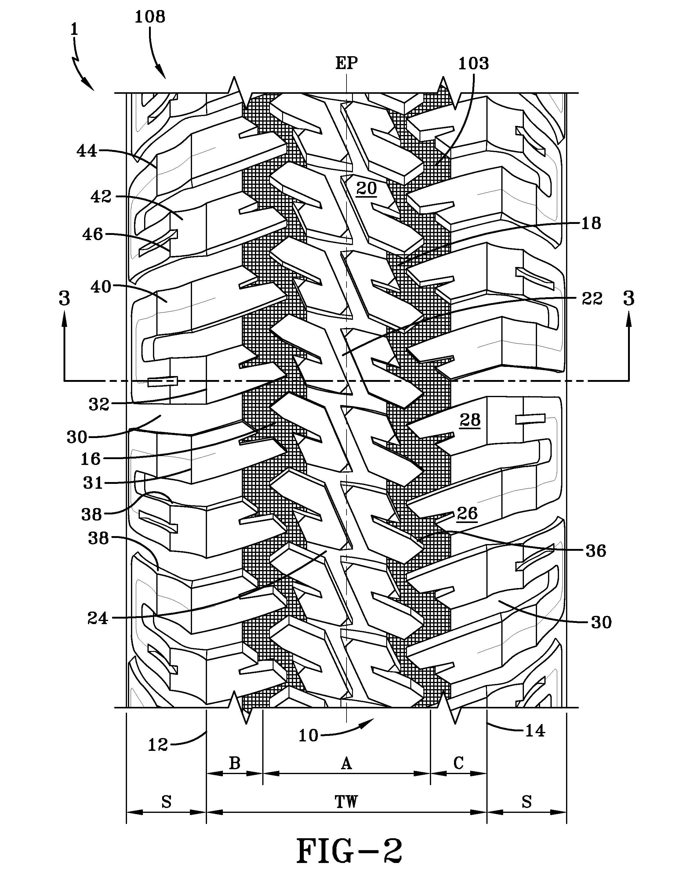
[0067]FIGS. 1-3 illustrate an example light truck tire 1. The tire 1 has a carcass 100 that extends between, and is turned up around, a pair of opposing beads 102. The carcass 100 is also located radially outward of an innerliner 104 that extends between opposing bead toes 106. A belt structure 110 is located radially outward of the carcass 100 and radially inward of the tire tread 108. The belt structure 110 comprises multiple plies of reinforcing cords. The example tire tread 108, as illustrated, has an on-road central tread portion 10 having a tread width TW, defined by a pair of first and second lateral edges 12, 14. Axially...


PUM


Abstract

The present invention is directed to a pneumatic tire comprising an axis of rotation and a tread. The tread has a plurality of traction elements and a discharge groove. The discharge groove has a base interposed between radially extending sides formed by side walls of the traction elements. The base of the discharge groove defines a matrix of circumferentially extending rectangular ramp structures. One ramp structure of the matrix extends circumferentially, from a radially inner first end portion, in a direction of rotation of the tire and radially outward to a radially outer second end portion. The radially outer second end portion defines an edge portion extending parallel to the axis of rotation of the tire. The edge portion improves traction of the tire and evacuation of the discharge groove.

Description

FIELD OF THE INVENTION [0001]The present invention is directed to the tread of a pneumatic tire. More specifically, the present invention is directed to light truck and passenger vehicle tires and texturing of the base of particular grooves of such tread.BACKGROUND OF THE INVENTION [0002]Over the last twenty years, off-road vehicle recreational activities have become increasingly popular. The number of off-road sporting events and rock crawling competitions has increased. Tires suitable for such events are typically heavily lugged tires, with large spacing for improved traction and a high number of biting surfaces to enable the tire to both grip the uneven terrain and to throw out any mud. Those tires used almost exclusively for such sporting events are manufactured with an enhanced construction to improve durability under severe conditions.[0003]Because of the popularity of such events, the look of the off-road tire has transitioned into use for conventional vehicle use. Light truc...

Claims


Application Information

Patent Timeline
IPC IPC(8): B60C11/13
CPCB60C11/01B60C11/13B60C11/11B60C11/0309B60C11/1353B60C2011/1361
Inventor BONKO, MARK LEONARDELSASS, JOSHUA RANDALLRENNER, JOHN DAVID
Owner BONKO MARK LEONARD
Learn More