Optical line monitoring apparatus and optical line monitoring method

a technology of optical line monitoring and optical line, applied in the direction of transmission monitoring, transmission monitoring/testing/fault measurement system, fibre optic/optical waveguide device testing, etc., can solve the problem of one or more minutes for one otdr measurement, inability to determine which optical line has failed, and inability to acquire information with regard, etc. problem, to achieve the effect of preventing an error detection, reducing the cost of calculation amount, and precise detection

Inactive Publication Date: 2009-07-30
THE FUJIKURA CABLE WORKS LTD
View PDF7 Cites 53 Cited by
  • Summary
  • Abstract
  • Description
  • Claims
  • Application Information

AI Technical Summary

Benefits of technology

[0073]Furthermore, in consideration of properties of an optical transmission line, when calculating a displacement amount of the second waveform portion from the first waveform portion, the shift amounts from any one of the first waveform portions are handled, to thereby make it possible to reduce the cost of a calculation amount much more than in the case of calculating the shift amount of all the waveform portions. Furthermore, a plurality of first waveform portions are taken as the reference waveforms. Thereby, even if a third waveform portion corresponding to one first wave portion fails to be detected as a result of a construction work, a break in a fiber, or the like, it is possible to automatically calculate a shift amount from another reference waveform. Therefo...

Problems solved by technology

Therefore, it was impossible to acquire information with regard to whether a failure occurred in an optical line between a first stage splitter and a second stage splitter or a failure occurred in an optical line between a second stage splitter and one of the terminators.
That is, there has been a problem in that it is impossible to determine which optical line has failed.
However, it takes about one or more minutes for one OTDR measurement.
The status monitoring apparatus is capable of monitoring whether a communication failure has occurred in an optical fiber line between the CATV center station and the monitoring unit, but is not capable of determining whether the failure is due to an optical signal transmission apparatus (for example, a relay amplifier, an optical signal transmission relay apparatus, a power source apparatus, or the like) from whether it is due to an optical fiber line.
However, it has a problem of taking more time than a given period of time to conduct a measurement.
In this case, even if there is a change in reflected light from one terminator, it is not possible to verify the change in reflected light intensity due to a reflected light from the other terminator.
At this time, there is a problem in that a large loss of optical lines causes a reduction in dynamic range, thus generating noise.
Especially in a branched line using a splitter, a great loss occurs in the splitter.
With a waveform with much noise, it is difficult to i...

Method used


Image

  • Optical line monitoring apparatus and optical line monitoring method
  • Optical line monitoring apparatus and optical line monitoring method
  • Optical line monitoring apparatus and optical line monitoring method

Examples


first embodiment

[0106]Hereinafter is a description of the present invention, with reference to the drawings.

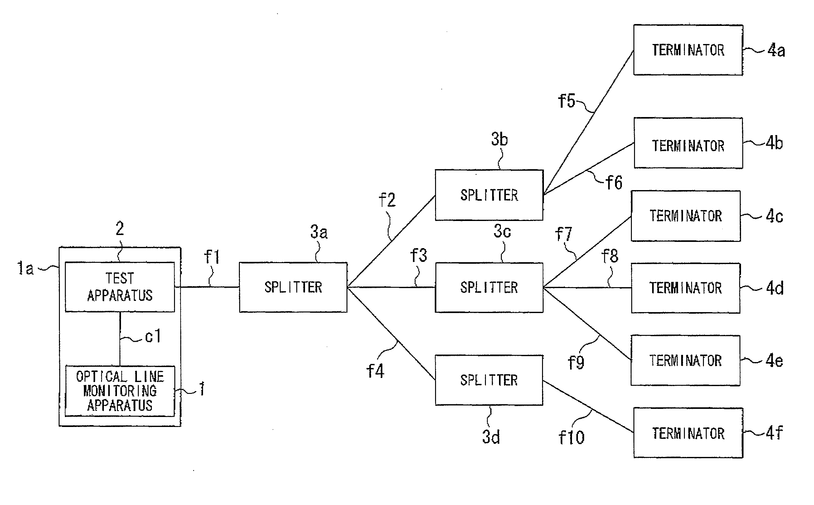
[0107]FIG. 1 is a schematic block diagram of an optical line monitoring system according to the first embodiment of the present invention. This optical line monitoring system includes: an optical line monitoring apparatus 1; a test apparatus 2; splitters 3 (3a, 3b, 3c, 3d); and terminators 4 (4a, 4b, 4c, 4d, 4e, 4f). In the first embodiment, the case where an OTDR (Optical Time Domain Reflectometer) is used as the test apparatus 2, and ONUs (Optical Network Units) are used as the terminators 4 is described.

[0108]The optical line monitoring apparatus 1 and the test apparatus 2 are connected via a cable c1 with a standard such as the RS232-C (Recommended Standard 232 version C), and is contained in one enclosure 1a. Furthermore, the test apparatus 2 and the splitter 3a are connected with an optical line f1. The splitter 3a and the splitters 3b, 3c, 3d are connected respectively with optical lin...

third embodiment

[0148]Next is a description of a second and third embodiment of the present invention with reference to the drawings.

[0149]FIG. 8 is a diagram for explaining an outline of an optical fiber line automatic 6 monitoring system according to the present invention. In FIG. 8, an optical fiber line 101 is a communication line made of one or more optical fiber cables 102. In the optical fiber cable 102, there is contained a plurality of optical fibers (coated optical fibers) 103. This optical fiber line 101 is connected to an optical signal transmission apparatus 104 which is for example a relay amplifier of a CATV network, a router of a TCP / IP network, or the like. It transmits image signals of CATV, digital packet signals, or the like as optical signals. To the optical signal transmission apparatus 104, there is provided a monitoring unit 105, which measures a received signal level and monitors an operation status or the like in the optical signal transmission apparatus 104.

[0150]Here, in...

second embodiment

[0157]FIG. 9 shows an exemplary configuration of an optical fiber line automatic monitoring system according to the present invention. In the figure, an exemplary configuration of an optical fiber line automatic monitoring system 120 is shown together with an exemplary configuration of a network monitoring apparatus 110. Only a portion directly related to the present invention is shown.

[0158]In the exemplary configuration shown in FIG. 9, the network monitoring apparatus 110 and the optical fiber line automatic monitoring system 120 are connected to each other via a communications line (a dedicated line, an ISDN line, or the like) 107 and a router 108. Alarm information is transmitted from the network monitoring apparatus 110 to the optical fiber line automatic monitoring system 120.

[0159]The network monitoring apparatus 110 is made of: a control portion (including a CPU) 111 for controlling the whole network monitoring apparatus 110; and a processing program portion 112. A monitori...


PUM


Abstract

An optical line monitoring apparatus, including: a group information recording portion which records group information about to which splitter respective terminators are connected; a normal information recording portion which records intensities of reflected lights from a plurality of terminators in a state in which a failure is not occurring in optical lines; a monitored information recording portion which records intensities of reflected lights from the plurality of terminators in failure monitoring time; an attenuation amount determination portion which determines a terminator the reflected light intensity of which is attenuated compared with the corresponding reflected light intensity in normal information; and a control portion which determines, if the intensities of the reflected lights of all the terminators connected to the same splitter are attenuated by the same value, that a failure has occurred between the test apparatus and the splitter to which all the terminators are connected.

Description

CROSS-REFERENCE TO RELATED APPLICATION[0001]This is a Continuation Application of International Application No. PCT / JP2007 / 051814, filed Feb. 2, 2007, which claims priority to Japanese Patent Application No. 2006-26763, filed on Feb. 3, 2006 and Japanese Patent Application No. 2006-291085, filed on Oct. 26, 2006 The contents of the aforementioned applications are incorporated herein by reference.FIELD OF THE INVENTION[0002]The present invention relates to an optical line monitoring apparatus and an optical line monitoring method which monitors a failure occurring in an optically branched line such as a PON (Passive Optical Network) transmission path which connects a test apparatus, a splitter, and a terminator, to an optical fiber line automatic monitoring system and an automatic optical fiber line monitoring method which can significantly reduce the time to restore a communication failure which has occurred in an optical fiber line, and to an optical transmission line monitoring ap...

Claims


Application Information

Patent Timeline
IPC IPC(8): H04B10/08H04B10/071
CPCH04B10/071G01M11/3136
Inventor NAKAJIMA, TOSHIAKIYASUHARA, KENJI
Owner THE FUJIKURA CABLE WORKS LTD
Why Eureka
Try Eureka