Relaying device, network system, and network system controlling method
a network system and control method technology, applied in the direction of electrical equipment, data switching networks, digital transmission, etc., can solve the problems of reducing inadequate innovation in the control of both the reliability of the data relay and the power consumption, and the power consumption is relatively large in the second power mod
- Summary
- Abstract
- Description
- Claims
- Application Information
AI Technical Summary
Benefits of technology
Problems solved by technology
Method used
Image

Examples
first embodiment
A. First Embodiment
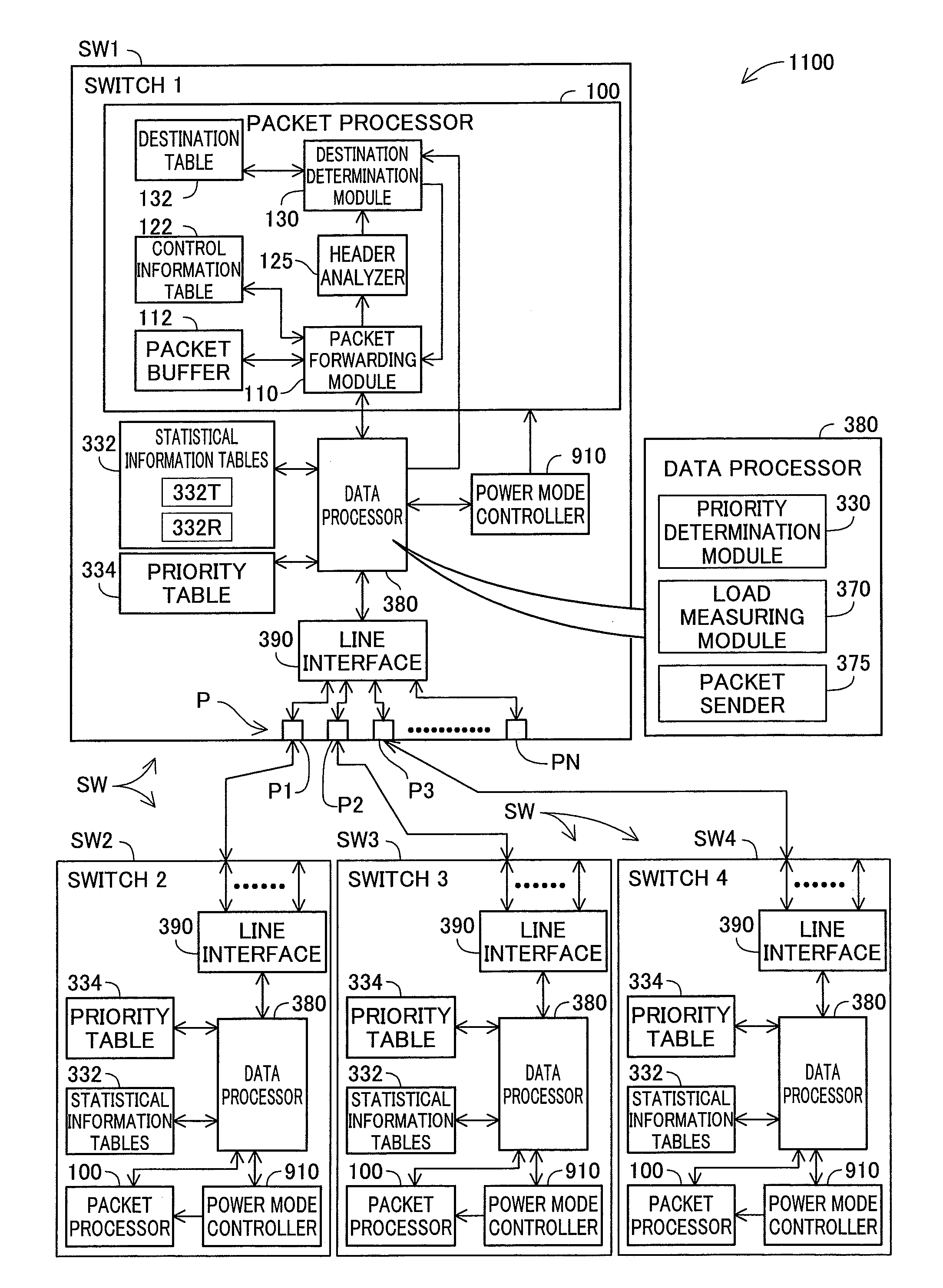
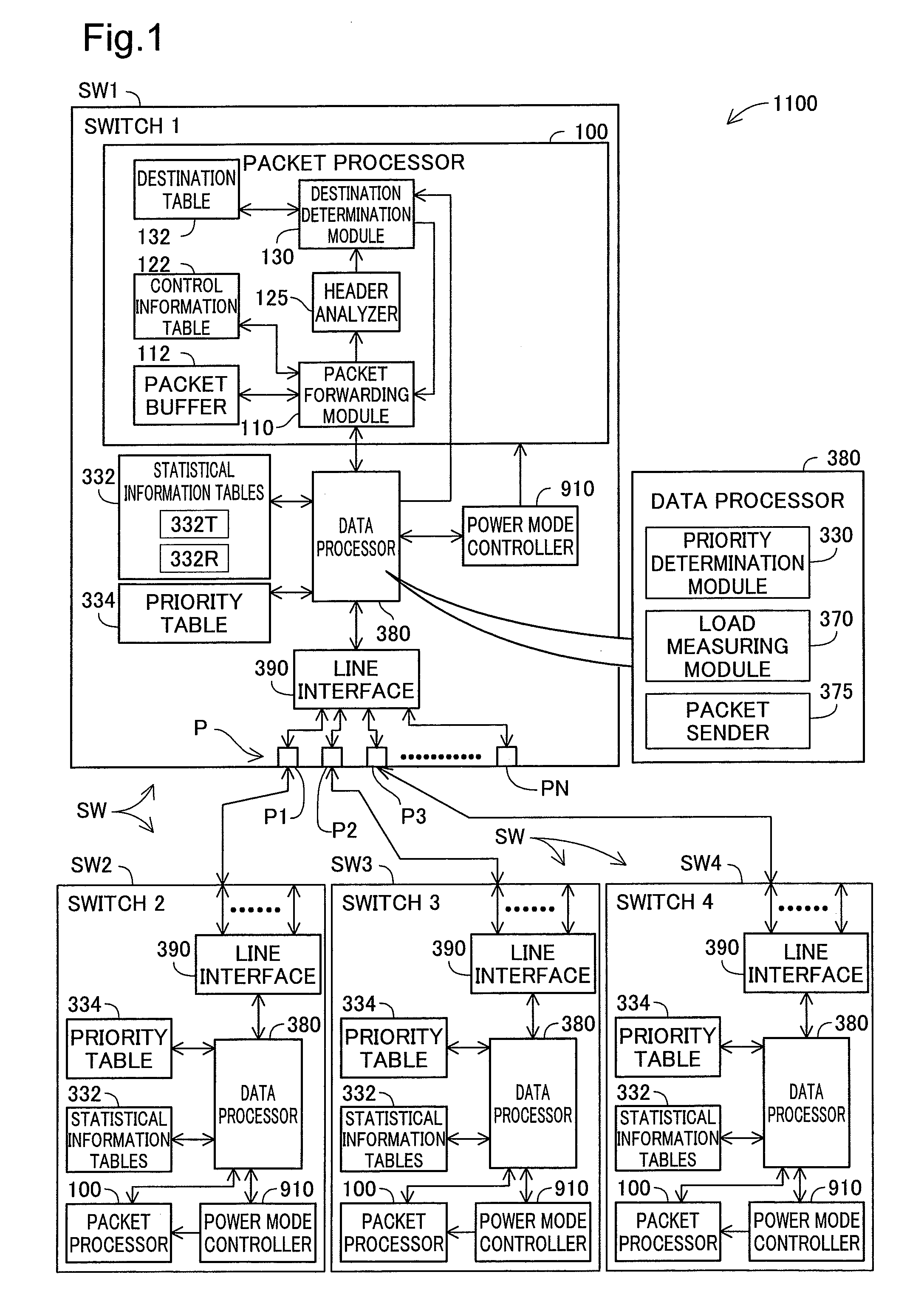
[0051]FIG. 1 is an explanatory diagram illustrating a network system 1100 as one embodiment according to the invention. This network system 1100 has four switching devices SW1, SW2, SW3, and SW4. In the embodiment, each switching device SW1, SW2, SW3, and SW4 functions as a so-called “layer 3 switch.” Layer 3 corresponds to the third layer (the network layer) in the so-called OSI (Open System Interconnection) reference model.
[0052]The configuration of the first switching device SW1 is illustrated in FIG. 1. The first switching device SW1 has a packet processor 100, a data processor 380, a line interface 390, a statistical information table 332, a priority table 334, a power mode controller 910, and N (where N is an integer at least 2) physical ports P. The statistical information table 332 includes a transmission statistical information table 332T and a reception statistical information table 332R. Each of these tables 332 and 334 is stored in a memory (not shown)...
second embodiment
B. Second Embodiment
[0146]FIG. 14 is an explanatory diagram illustrating another embodiment of switching the selecting mode. In contrast to the embodiment illustrated in FIG. 11, in the embodiment, the destination determination module 130 determines the selecting mode in accordance with the two conditions SCa and SCb, illustrated below. The processes aside from the selecting mode determination (FIG. 11: S320) are the same as those in the first embodiment illustrated in FIG. 10 through FIG. 12. Furthermore, the configurations in the network system 1100 are the same as those in the first embodiment illustrated in FIG. 1.
[0147]The conditions SCa and SCb used in the embodiment are as set forth below:
[0148](First Switching Condition SCa) The total output load on the selectable port list is greater than or equal to the selecting upper limit.
[0149](Second Switching Condition SCb) The total output load on the selectable port list is less than or equal to the selecting lower limit.
[0150]Here...
third embodiment
C. Third Embodiment
[0157]FIG. 15 is an explanatory diagram of a data processor 380a as set forth in a third embodiment. The difference from the data processor 380 illustrated in FIG. 1 is only in the point that a power mode instructing module 360 is added. The other configurations are the same as those in the data processor 380 illustrated in FIG. 1. The configuration of the network system in the third embodiment is the same as that of the network system 1100 in FIG. 1, with the exception of the point that the data processor 380 is replaced by the data processor 380a.
[0158]In the third embodiment, the packet processing is the same as that of the second embodiment illustrated in FIG. 10, FIG. 11, and FIG. 14. Furthermore, in the third embodiment, a mode changing packet transmitting process is performed in addition to the processes in FIG. 10 and FIG. 11. FIG. 16 is a flowchart illustrating the procedure of the mode changing packet transmitting process. This process is a process that...
PUM
 Abstract
Description
Claims
Application Information
 - R&D
- Intellectual Property
- Life Sciences
- Materials
- Tech Scout
- Unparalleled Data Quality
- Higher Quality Content
- 60% Fewer Hallucinations
Browse by: Latest US Patents, China's latest patents, Technical Efficacy Thesaurus, Application Domain, Technology Topic, Popular Technical Reports.
© 2025 PatSnap. All rights reserved.Legal|Privacy policy|Modern Slavery Act Transparency Statement|Sitemap|About US| Contact US: help@patsnap.com