
Concentric hollow cathode magnetron sputter source

a hollow cathode magnetron and sputter source technology, applied in the field of sputter source, can solve problems such as and achieve the effect of reducing ion and electron damage to the substra

Inactive Publication Date: 2009-07-30
4D S
View PDF5 Cites 1 Cited by
  • Summary
  • Abstract
  • Description
  • Claims
  • Application Information

AI Technical Summary

Benefits of technology

[0005]A new sputter source is disclosed that allows for high rates of deposition at pressures one or two orders of magnitude lower than has previously been obtained. This results in denser films with reduced ion and electron damage to the substrate.

Problems solved by technology

This results in denser films with reduced ion and electron damage to the substrate.

Method used


Image

  • Concentric hollow cathode magnetron sputter source
  • Concentric hollow cathode magnetron sputter source
  • Concentric hollow cathode magnetron sputter source

Examples


Embodiment Construction

[0010]The present invention relates generally to a sputter source and more specifically to a magnetron sputter source, the deposition of materials and more specifically to utilizing a sputter source for the deposition of the material. The following description is presented to enable one of ordinary skill in the art to make and use the invention and is provided in the context of a patent application and its requirements. Various modifications to the preferred embodiments and the generic principles and features described herein will be readily apparent to those skilled in the art. Thus, the present invention is not intended to be limited to the embodiments shown, but is to be accorded the widest scope consistent with the principles and features described herein.

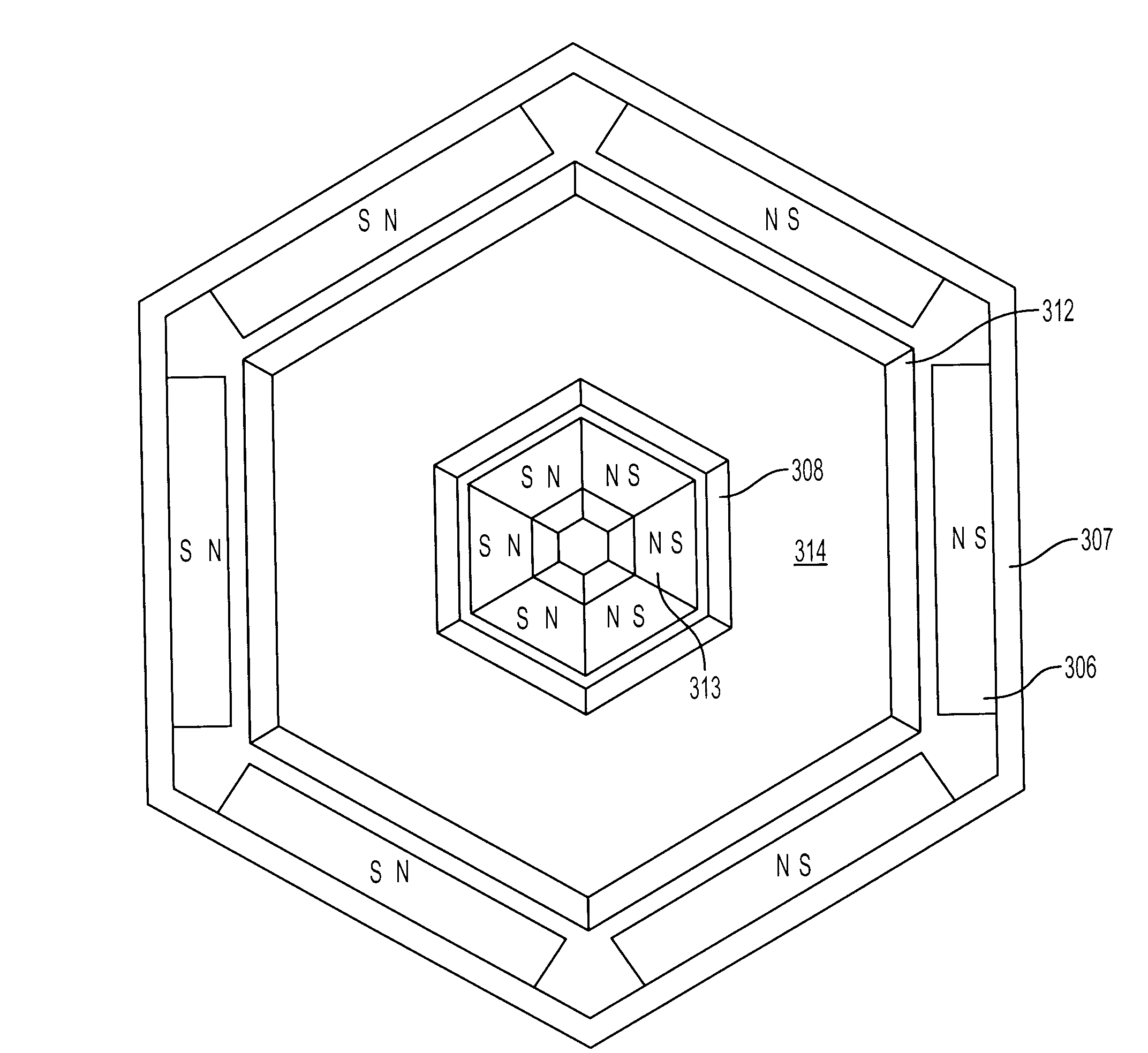
[0011]The present invention is a “Concentric Hollow Cathode Sputter Source” and is shown in FIG. 3. FIG. 3 is a cross section of the sputter source 300 which consists of a circular housing 302. A outer hexagon ring of two rows ...


PUM

PropertyMeasurementUnit
magnetic fieldaaaaaaaaaa

Abstract

A new sputter source is disclosed that allows for high rates of deposition at pressures one or two orders of magnitude lower than has previously been obtained. This results in denser films with reduced ion and electron damage to the substrate.

Description

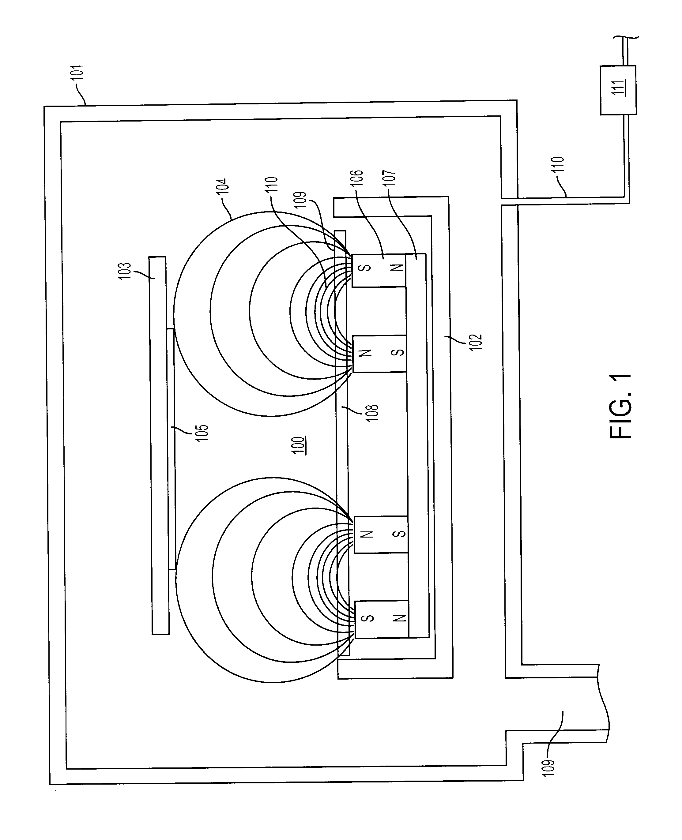
FIELD OF THE INVENTION[0001]The present invention relates generally to a sputter source and more specifically to a magnetron sputter source, the deposition of materials and more specifically to utilizing a sputter source for the deposition of the material.BACKGROUND OF THE INVENTION[0002]The deposition of materials using a magnetron enhanced sputter source has been used for more than 30 years. The cross section of a typical circular magnetron sputter source is shown in FIG. 1. The sputter source 100 is placed in a vacuum chamber 101. The vacuum chamber 101 is attached to a vacuum pump (not shown) through a port 109. Magnets 106 are arranged in 2 concentric rings and attached to an iron yoke 107 resulting in a strong magnetic field 104 that penetrates the target 108 and is largely parallel 110 with the target surface 109. The strong magnetic field 110, typically >300 gauss, parallel to the target surface 109 traps the gas ions near the target surface 109 resulting in an increase o...

Claims


Application Information

Patent Timeline
Patent Type & Authority Applications(United States)
IPC IPC(8): C23C14/35
CPCC23C14/3407H01J37/3452H01J37/3405H01J37/32596
Inventor BRORS, DANIELSCHMIDT, DOMINIKHAWRAN, MICHAELCORREIA, DAVESHULENBERGER, ART
Owner 4D S
Learn More