
Control mechanism for a power tool

Active Publication Date: 2009-07-30
BLACK & DECKER INC
View PDF13 Cites 17 Cited by
  • Summary
  • Abstract
  • Description
  • Claims
  • Application Information

AI Technical Summary

Benefits of technology

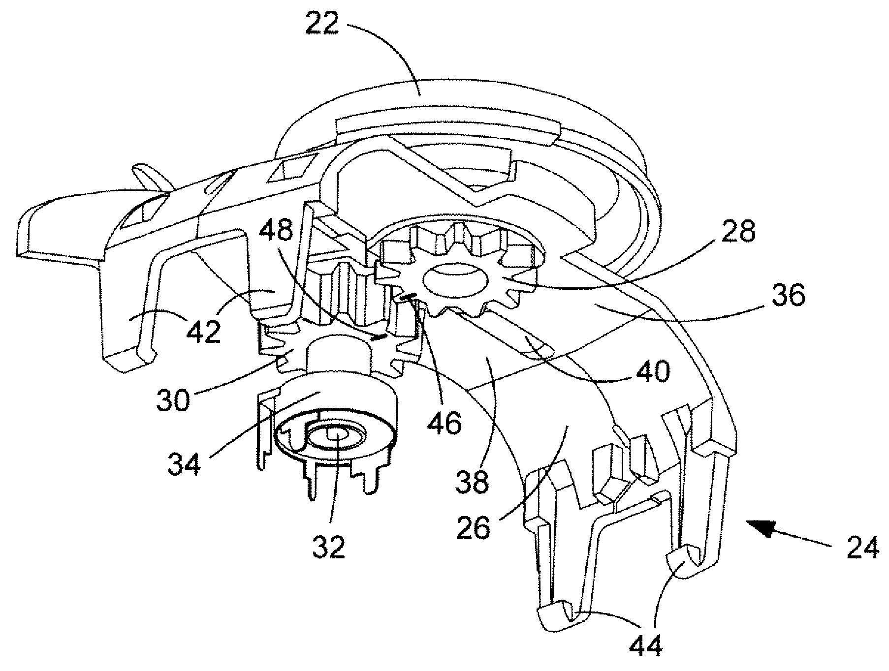
[0009]a second rotary member having a second axis of rotation, not coincident with said first axis of rotation, and adapted to rotate as a result of rotation of said first rotary member to transfer torque from said first rotary member to an input of a control circuit of the power tool to adjust a setting of the tool, wherein limited movement of said first rotary member relative to said second rotary member is possible to reduce transmission of impacts from the adjustment dial to the input of a control circuit.
[0037]a second rotary member having a second axis of rotation, not coincident with said first axis of rotation, and adapted to rotate as a result of rotation of said first rotary member to transfer torque from said first rotary member to an input of the control circuit to adjust a setting of the tool, wherein limited movement of said first rotary member relative to said second rotary member is possible to reduce transmission of impacts from the adjustment dial to the control circuit.

Problems solved by technology

However, such tools suffer from the disadvantage that impacts on the dial, for example as a result of a user dropping the tool, can cause damage which can be expensive to repair.
In particular, if the tool should be dropped onto its speed adjustment dial, the impact force can be transmitted down a shaft attached to the dial and into the variable resistor, causing further damage to the electrical components of the tool, which significantly increases the cost of repair of the tool.

Method used


Image

  • Control mechanism for a power tool
  • Control mechanism for a power tool
  • Control mechanism for a power tool

Examples


second embodiment

[0107]a side handle assembly embodying the present invention is shown in FIG. 14, in which pairs of resilient vibration damping members 152 are provided in the recesses 150 in the support 100. Similar vibration damping members (not shown) can be provided in the recesses 138 on the flange 136 of the handle 84.

third embodiment

[0108]a side handle assembly embodying the present invention is shown in FIG. 15, in which pairs of resilient vibration damping members 154 are provided on the first and second pegs 142, 146 on the locking ring 140.

fourth embodiment

[0109]a side handle assembly embodying the present invention is shown in FIG. 16, in which a strip 156 of resilient material is provided on the inner surface of the metal strip 82, in order to damp vibrations transmitted from the outer housing 4 of the hammer drill 2 to the metal strip 82.

[0110]A known two torque clutch connected between a motor output shaft and a spindle drive of the hammer drill of FIG. 1 is disclosed in WO 2004 / 024398. A similar clutch will now be described in more detail with reference to FIGS. 17 to 19.

[0111]A bevel gear 158 which forms part of the clutch arrangement is integrally formed with a shaft 160 of circular cross section. The upper end of the shaft 160 is rotatably mounted within the housing 4 of the hammer via a bearing comprising an inner race 162 which is rigidly attached to the shaft 160, an outer race 164 which is rigidly attached to the housing and ball bearings 166 which allow the outer race 164 to freely rotate about the inner race 162. The bea...


PUM

PropertyMeasurementUnit
Speedaaaaaaaaaa

Abstract

A speed adjustment mechanism for a power tool is disclosed. The mechanism includes a support, a first toothed gear for rotation by means of an adjustment dial, and a second toothed gear rotatable by means of the first toothed gear and connected to a potentiometer which is connected to a speed control circuit. Limited movement of the first and second toothed gears relative to each other is possible to reduce transmission of impacts from the adjustment dial to the speed control circuit.

Description

CROSS-REFERENCE TO RELATED APPLICATIONS[0001]This application claims priority, under 35 U.S.C. § 119(a)-(d), to UK Patent Application No. GB 08 013 05.4 filed Jan. 24, 2008, the contents thereof to be incorporated herein by reference in its entirety.FIELD OF THE INVENTION[0002]The present invention relates to a control mechanism for a power tool, and relates particularly, but not exclusively, to a mechanism for controlling the speed of rotation of a drill bit and hammer frequency of a hammer drill. The invention also relates to a power tool incorporating such a control mechanism.BACKGROUND OF THE INVENTION[0003]Power tools are known which are provided with a continuously variable rotary dial to control a function of the power tool. For example, the rotational speed and hammer frequency of a hammer drill can be controlled by turning a rotary dial, thereby varying the resistance of a variable resistor. A hammer drill of this type is disclosed in U.S. Pat. No. 4,454,459.[0004]However, ...

Claims


Application Information

Patent Timeline
IPC IPC(8): B25D11/00E21B3/00
CPCB25D16/003B25D16/006B25D17/043B25D17/24B25D2211/061B25D2250/065H01C10/14B25D2250/165B25D2250/201B25F5/001B25F5/006B25F5/026B25D2250/155
Inventor GUMPERT, RENEGROSSMAN, HORSTRUETHERS, BRUNO
Owner BLACK & DECKER INC
Learn More