
Method and device for storing data on a record medium and for transferring information

a record medium and data technology, applied in the field of optical storage, can solve the problems of not being able to actually give a header write command to the host, and the header portion of a sector is not user-accessibl

Inactive Publication Date: 2009-07-23
KONINKLIJKE PHILIPS ELECTRONICS NV
View PDF6 Cites 2 Cited by
  • Summary
  • Abstract
  • Description
  • Claims
  • Application Information

AI Technical Summary

Benefits of technology

[0013]However, the header portion of a sector is not user-accessible, i.e. a host has no direct control over the contents of a header portion. Thus, it is not possible for the host to actually give a header write command to the disc.

Problems solved by technology

However, the header portion of a sector is not user-accessible, i.e. a host has no direct control over the contents of a header portion.
Thus, it is not possible for the host to actually give a header write command to the disc.

Method used


Image

  • Method and device for storing data on a record medium and for transferring information
  • Method and device for storing data on a record medium and for transferring information
  • Method and device for storing data on a record medium and for transferring information

Examples


example 1

WRITE (12) Command (W12)

[0035]FIG. 5 is a table illustrating a W12 command descriptor block, adapted in accordance with the present invention.

[0036]As illustrated by the table in FIG. 5, the W12 command comprises 12 bytes of 8 bits each. Byte 0 contains an operation code, bytes 2-5 are used to indicate the logical block address of the storage space where the data sector 30 should be stored, and bytes 6-9 are used to indicate the length of the data sector 30 to be transferred. Byte 11 is a control byte.

[0037]Bits 5-7 of byte 1, and bytes 0-6 of byte 10 are reserved for later definition, i.e. they do not have a defined meaning yet. So, it is possible to use any one of these bits as an encryption bit EB, indicating that the W12 command is to be taken as a write encrypted sector command WESC.

[0038]In the embodiment as illustrated in FIG. 5, the first four bits 0-3 of byte 10 are used as an encryption key identifier EKI. The value EKI=0 means “no encryption”, which is compatible with cur...

example 2

READ (12) Command (R12)

[0048]FIG. 7 is a table illustrating a R12 command descriptor block, adapted in accordance with the present invention.

[0049]As illustrated by the table in FIG. 7, the R12 command comprises 12 bytes of 8 bits each. Byte 0 contains an operation code, bytes 2-5 are used to indicate the logical block address of the storage space where the data sector 30 should be read, and bytes 6-9 are used to indicate the length of the data sector 30 to be transferred. Byte 11 is a control byte.

[0050]Bits 5-7 of byte 1, and bytes 0-6 of byte 10 are reserved for later definition, i.e. they do not have a defined meaning yet. So, it is possible to use any one of these bits as an encryption bit, indicating that the R12 command is to be taken as a read encrypted sector command RESC.

[0051]In the embodiment as illustrated in FIG. 7, the first four bits 0-3 of byte 10 are used as an encryption key identifier EKI. The value EKI=0 means “no encryption”, which is compatible with current ho...


PUM

PropertyMeasurementUnit
block structureaaaaaaaaaa
physical address PAaaaaaaaaaa
physicalaaaaaaaaaa

Abstract

Data storage system (1) comprises: an optical disc (2) having a storage space (3) for receiving sectors of data; a disc drive (10), suitable for writing information to the disc; a host (20), capable of cooperating with the drive; the host being designed to send to said drive a write encrypted sector command WESC(EKI) for commanding said drive to write one or more bus-encrypted sectors to said disc, WESC(EKI) including an encryption key identifier EKI; the drive being designed, in response to receiving said WESC(EKI), to evaluate the value of EKI, and, if the value of EKI indicates a bus-encrypted user data portion (32E), to decrypt this user data portion, to generate a header portion (31) with bus encryption information BEI, to combine this header portion with the decrypted user sector portion (32) to make a data sector (30), and to write the data sector (30) to the disc.

Description

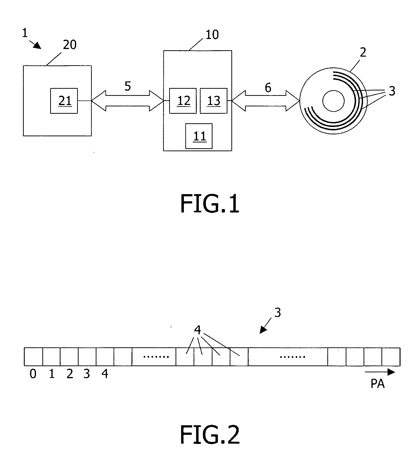
FIELD OF THE INVENTION[0001]The present invention relates in general to the field of storing data on a record medium. The present invention relates particularly to the field of optical storage, such as CD, DVD, BluRay, and the invention will be explained hereinafter for the case of BluRay, but it is to be noted that this is by way of example only and is not intended to restrict the scope of the invention. The gist of the present invention is also applicable to other types of recordable discs, either optical or not, and the gist of the present invention is even applicable to recordable media other than disc type.BACKGROUND OF THE INVENTION[0002]Since the technology of optical data storage in general, including the way in which information can be stored in an optical disc, is commonly known, it is not necessary here to explain this technology in great detail. It is briefly summarized that an optical storage disc comprises at least one track, either in the form of a continuous spiral o...

Claims


Application Information

Patent Timeline
Patent Type & Authority Applications(United States)
IPC IPC(8): G11B19/04G06F21/80
CPCG06F21/80G11B20/00507G11B20/0021G11B20/00086G11B20/00G06F17/00G11B20/10G06F21/00
Inventor BRONDIJK, ROBERT ALBERTUS
Owner KONINKLIJKE PHILIPS ELECTRONICS NV
Learn More