
Image display apparatus

Inactive Publication Date: 2009-07-23
SONY CORP
View PDF31 Cites 3 Cited by
  • Summary
  • Abstract
  • Description
  • Claims
  • Application Information

AI Technical Summary

Benefits of technology

[0009]The present invention is accomplished in view of the foregoing circumstance, and aims to provide an easy-to-use image display apparatus.
[0011]According to the embodiment of the present invention, the rod can easily be moved to the falling-down position and to the standing position without using a tool such a driver, whereby the usability of the image display apparatus can be enhanced.
[0012]The first posture and the second posture of the casing can be formed by placing the leading end of the rod, which is defined as the standing position, and the side of the casing on the placing surface. Therefore, the degree of freedom in enjoying the image can be enhanced, which is advantageous in enhancing practical value of the image display apparatus.
[0013]Since the stand is formed of the rod, the appearance of the stand is good, and the appearance property of the image display apparatus can be enhanced.

Problems solved by technology

Therefore, when the image display apparatus is housed, the leg protrudes from the rear surface if the leg remains mounted, which is disadvantageous in housing property.
Although the image display apparatus can be housed with the leg removed, the screw has to be removed by using a tool such as a driver, which is inconvenient.

Method used


Image

  • Image display apparatus
  • Image display apparatus
  • Image display apparatus

Examples


Embodiment Construction

[0041]An embodiment of the present invention will be described with reference to the drawings.

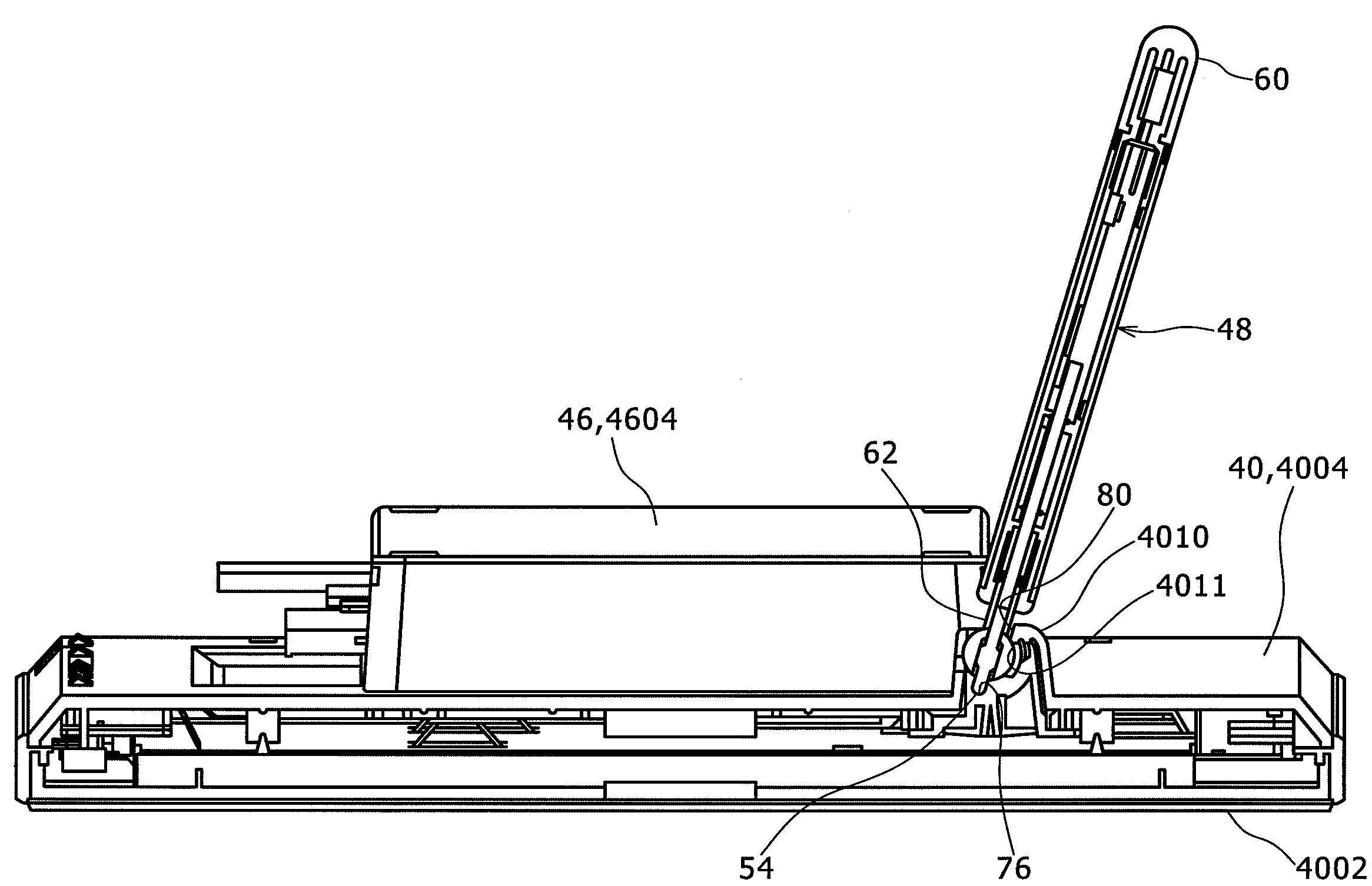
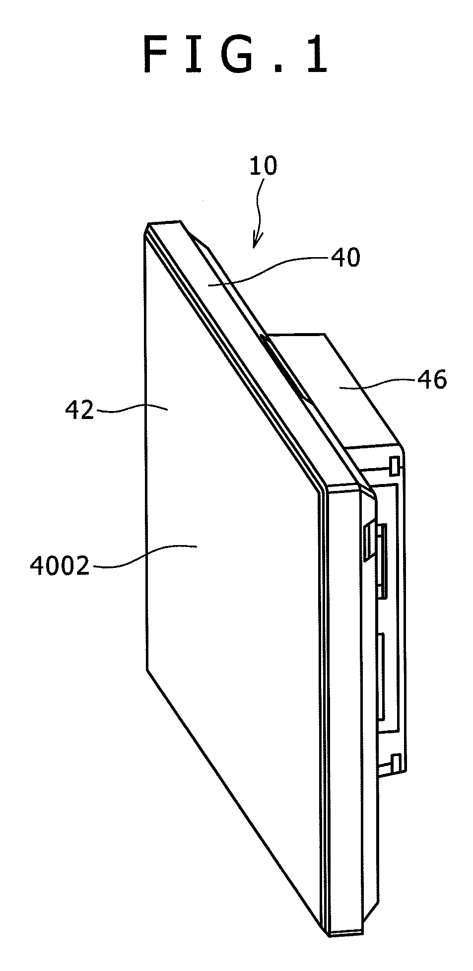
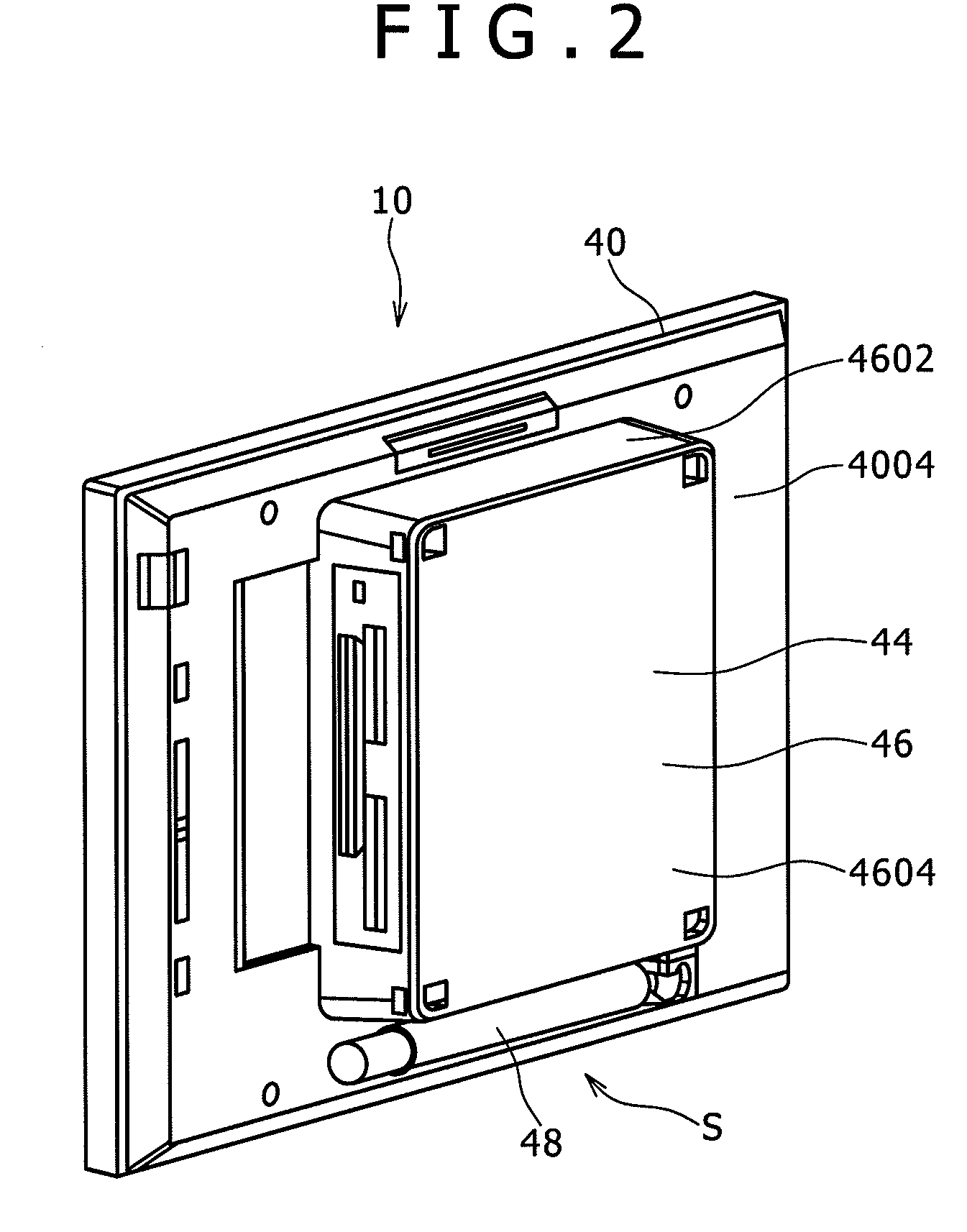
[0042]As shown in FIGS. 1 and 2, an image display apparatus 10 includes a casing 40, a display surface 42, a stand S, an image display section 44, and the like.

[0043]A control system of the image display apparatus 10 will firstly be described. As shown in FIG. 8, the image display apparatus 10 includes a built-in memory 12, a connector 14 for a recording medium, an external interface connector 16, interfaces 18, 20 and 22, a display driver 24, a display 26, an operation section 28, a posture sensor 30, a control section 34, and the like.

[0044]The built-in memory 12 is made of a rewritable recording medium such as a flash EEPROM, whereby image data can be written to or read from the built-in memory 12 through the interface 18 by the control section 34.

[0045]The connector 14 for a recording medium has attached thereto a recording medium 32 having portability such as a memory card.

[0046]The re...


PUM


Abstract

An image display apparatus includes a casing, a stand, and an image display section. The stand is formed of a single rod. The image display apparatus further includes a link mechanism that links the rod and a portion of the rear surface, supports the rod so as to be pivotal between a falling-down position where the rod falls down on the rear surface and a standing position where the rod stands from the rear surface, and locks and holds the rod to the falling-down position and the standing position. The rod is located at the standing position and one of two long sides of the casing and the leading end of the rod are placed onto a placing surface, whereby a first posture in which the casing stands with a first angle with respect to the placing surface is formed. The rod is located at the standing position and one of two short sides of the casing and the leading end of the rod are placed onto the placing surface, whereby a second posture in which the casing stands with a second angle with respect to the placing surface is formed.

Description

CROSS REFERENCE TO RELATED APPLICATION[0001]The present invention contains subject matter related to Japanese Patent Application JP 2008-011094 filed in the Japanese Patent Office on Jan. 22, 2008, the entire contents of which being incorporated herein by reference.BACKGROUND OF THE INVENTION[0002]1. Field of the Invention[0003]The present invention relates to an image display apparatus.[0004]2. Description of the Related Arts[0005]An image display apparatus has been proposed as a device by which a user readily enjoys image data recorded on a recording medium such as a memory card by means of a digital still camera or the like.[0006]The proposed image display apparatus has a configuration including a display surface on which an image is displayed on a front surface of a rectangular flat casing, and an image display section that allows the image read from the memory card to be displayed on the display surface (see, for example, JP 2000-148440).[0007]When a user enjoys an image by usi...

Claims


Application Information

Patent Timeline
IPC IPC(8): H01K5/00
CPCF16M13/00F16M11/10F16M11/105F16M13/005F16M2200/024F16M2200/08
Inventor NUMATA, KOICHIBUNYA, TAKASHIENDOH, TAKUMI
Owner SONY CORP
Learn More