Rear vehicle body structure

Inactive Publication Date: 2009-07-23
HONDA MOTOR CO LTD
View PDF13 Cites 2 Cited by
  • Summary
  • Abstract
  • Description
  • Claims
  • Application Information

AI Technical Summary

Benefits of technology

[0007]A second object of the present invention is to provide a rear vehicle body structure which can favorably distribute a load of a rear end crash.
[0008]A third object of the present invention is to provide a rear vehicle body structure which can effectively control the deformation a passenger compartment at the time of a rear end crash.
[0011]Owing to the provision of the rear vertical frames, even when a rear end crash is caused by a vehicle having a front bumper at a relatively high position, the vehicle body structure according to the present invention is able to evenly distribute the impact energy of the rear end crash, and the deformation of the passenger compartment can be minimized even when the present invention is applied to a small hatchback passenger vehicle lacking in a rear bulkhead for separating the passenger compartment from a luggage compartment. Also, the rear horizontal frames allow the impact energy of a rear end crash to be transmitted to the door beams, and this contributes to the reinforcement of the passenger compartment against deformation.

Problems solved by technology

However, the distribution of the load of a rear end collision is not necessarily optimally distributed depending on the mode of the rear end collision, and there is no effective measure against a rear end crash by a taller vehicle.
This provides a measure against a rear end crash by a taller vehicle and promotes a favorable distribution of a load of a rear end crash, but these effects are not entirely satisfactory.
Furthermore, this arrangement requires some space between the rear seat and rear cross member which a small hatchback passenger vehicle cannot afford.

Method used


Image

  • Rear vehicle body structure
  • Rear vehicle body structure
  • Rear vehicle body structure

Examples


Embodiment Construction

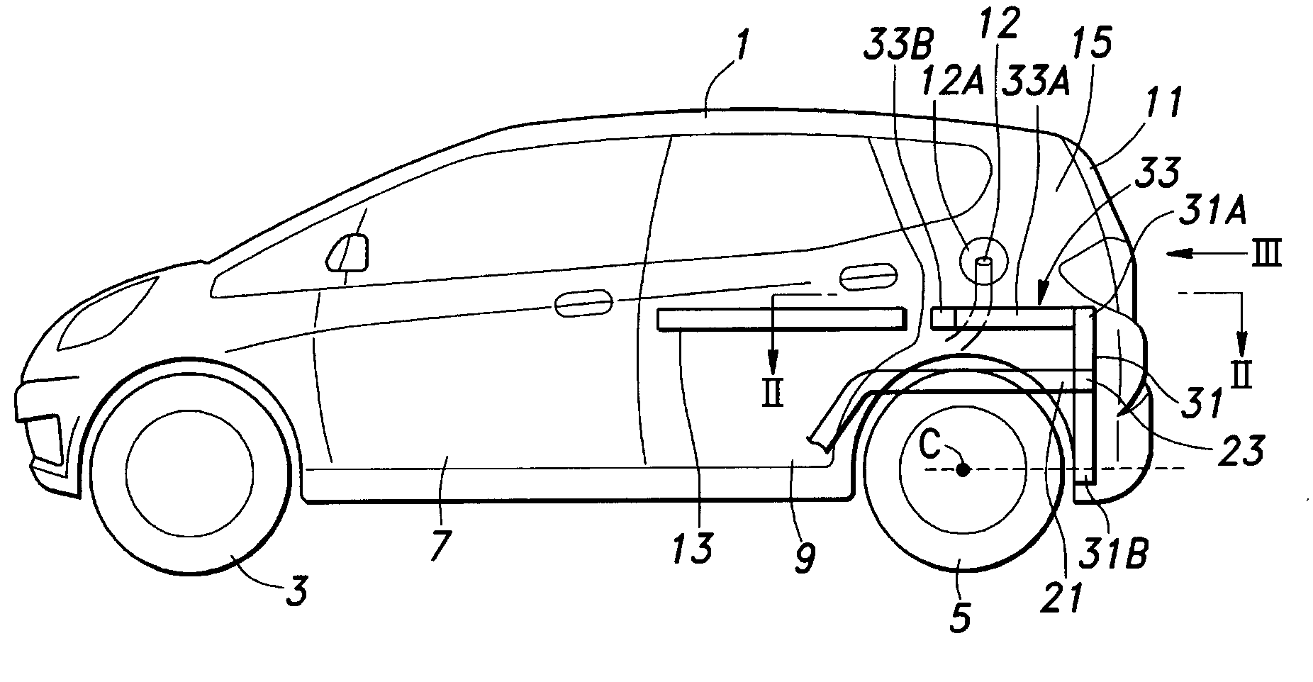
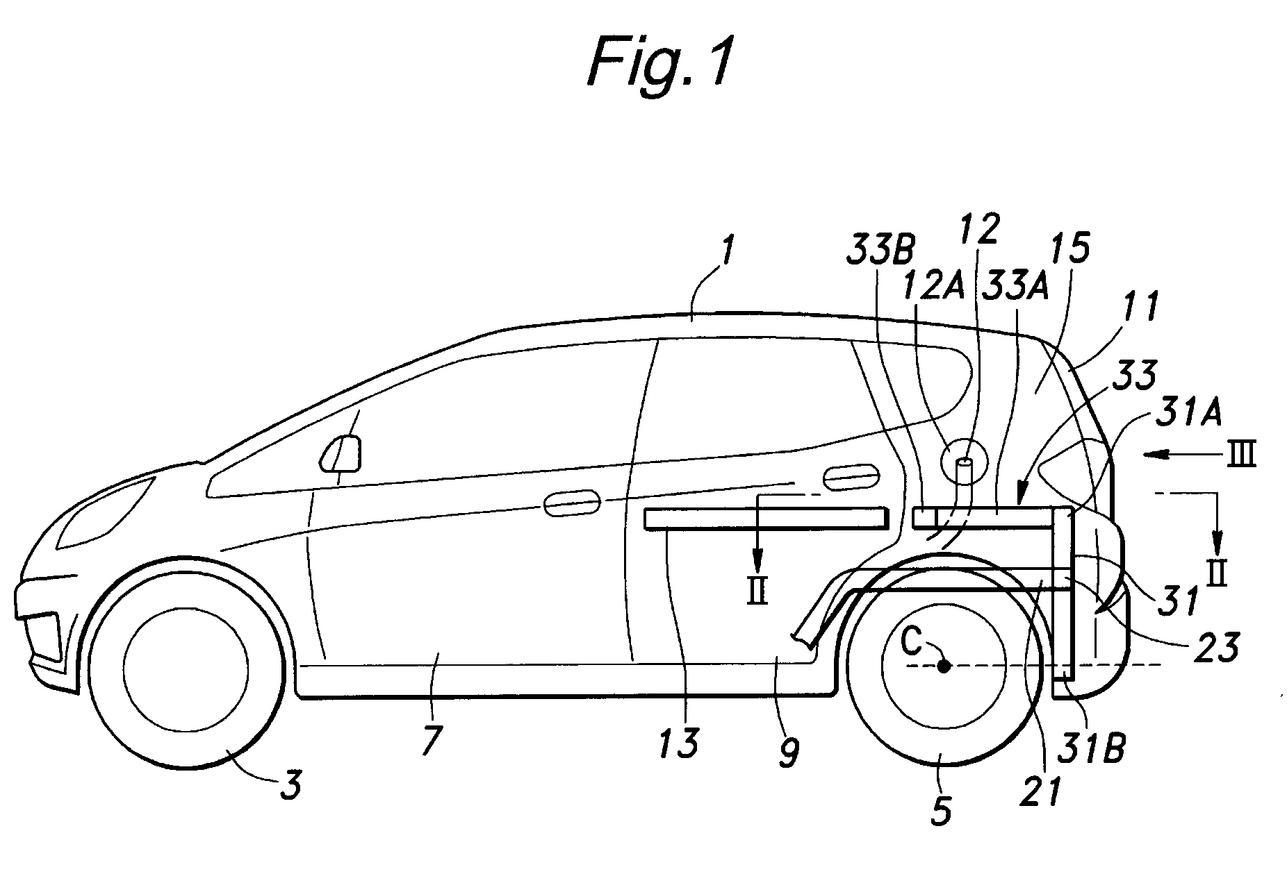
[0020]FIG. 1 shows the overall structure of a hatchback passenger vehicle having a rear vehicle body structure embodying the present invention. This vehicle comprises a pair of front wheels 3, a pair of rear wheels 5 and a vehicle body 1 fitted with a pair of front side doors 7, a pair of rear side doors 9 and a tailgate 11.

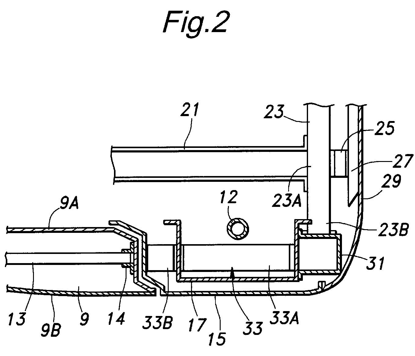
[0021]Each rear side door 9 includes a door inner panel 9A, a door outer panel 9B and a door beam 13 extending horizontally in a fore-and-aft direction at a prescribed height within a cavity defined between the door inner panel 9A and door outer panel 9B for reinforcement. The front end of the door beam 13 is attached to a front part of the door inner panel 9A, and the rear end of the door beam 13 is attached to a rear part of the door inner panel 9A via a bracket 14 in each case.

[0022]The rear vehicle body comprises a pair of rear outer side panels 15, a pair of rear inner side panels 17, a pair of rear floor frames 21 extending in the fore-and-aft direction of ...


PUM


Abstract

A pair of rear floor frames extend in a fore-and-aft direction in a lower part of a vehicle body. A pair of rear horizontal frames extend in the fore-and-aft direction above corresponding rear wheels. A door beam extends in the fore-and-aft direction in each side door in alignment with the corresponding rear horizontal frame. A pair of rear vertical frames each extend vertically behind the corresponding rear wheel and join rear ends of the corresponding rear floor frame and rear horizontal frame to each other. In a rear end crash with a vehicle having a front bumper at a relatively high position, the rear vertical frames allow the impact energy of the rear end crash to be evenly distributed, and deformation of the passenger compartment is minimized. The rear horizontal frames allow the impact energy to be transmitted to the door beams, contributing to reinforcement of the passenger compartment.

Description

TECHNICAL FIELD[0001]The present invention relates to a rear vehicle body structure, and in particular to a rear vehicle body structure suitable for a hatchback passenger vehicle that has no rear bulkhead for separating a rear luggage compartment from a passenger compartment.BACKGROUND OF THE INVENTION[0002]Japanese patent laid open publication (kokai) No. 2004-322822 discloses a rear vehicle body structure suitable for a hatchback passenger vehicle that has no rear bulkhead for separating a rear luggage compartment from a passenger compartment. Each rear floor frame of this rear vehicle body structure comprises a kickup portion that is bent upward from a rear end of the rear floor frame and extends horizontally and a reinforcement that extends horizontally below the kickup portion in a parallel relationship, and the rear ends of these frame members are connected to a rear pillar. A suspension support member extends in a fore-and-aft direction of the vehicle body between the rear pi...

Claims


Application Information

Patent Timeline
IPC IPC(8): B62D25/08
CPCB62D25/08
Inventor TSUYUZAKI, TAKUMIYAMAGUCHI, TOSHIZUMINUSHII, HIRO
Owner HONDA MOTOR CO LTD
Why Eureka
Try Eureka