
Electrode with Improved Plasma Uniformity

a technology of plasma uniformity and electrodes, applied in the field of electrodes, can solve the problems of affecting the uniformity of plasma and film-coating rate, seriously affecting the efficiency and cost of mass production, and achieve the effect of improving plasma uniformity

Inactive Publication Date: 2009-07-23
CONTREL TECH CO LTD
View PDF0 Cites 0 Cited by
  • Summary
  • Abstract
  • Description
  • Claims
  • Application Information

AI Technical Summary

Benefits of technology

[0007]Hence, an aspect of the present invention is directed to an electrode with improved plasma uniformity, and the electrode has an adjustable electric field for use in film deposition and etching processes conducted in plasma apparatuses.
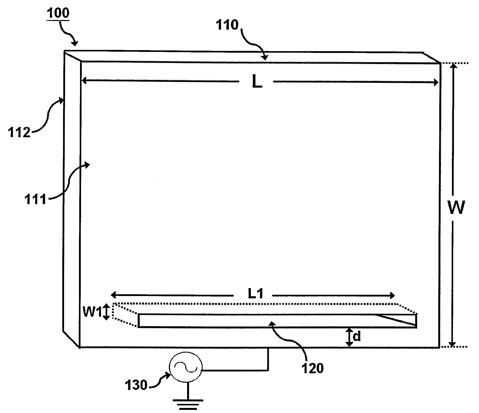
[0008]According to an embodiment of the present invention, an electrode with improved plasma uniformity is provided for use in a chamber generating which can generate plasma. The electrode comprises an electrode plate and a perturbation slot segment. The electrode plate has a first surface and a second surface opposite to the first surface, wherein the electrode plate is electrically connected to a radio frequency (RF) current source for generating an electric field. The perturbation slot segment is adjacent to a side of the electrode plate, and is symmetrically formed from the first surface to the second surface for controlling the intensity distribution of said electric field. The perturbation slot segment is located at the same side with the RF current source.

Problems solved by technology

However, when the area of a substrate desired to be film-coated increases, the electromagnetic wave propagated thereon will cause the variation of electric field due its phase change, thus relatively affecting the plasma uniformity and film-coating rate.
Especially when the size of the current film-coated substrate has increased from an eight or twelve-inch wafer to a large-area glass substrate (greater than 1 m2) developed in the current TFT factory or solar energy manufacturer, the aforementioned problem will seriously affect the efficiency and cost of mass production.

Method used


Image

  • Electrode with Improved Plasma Uniformity
  • Electrode with Improved Plasma Uniformity
  • Electrode with Improved Plasma Uniformity

Examples


Embodiment Construction

[0024]Reference will now be made in detail to the present preferred embodiments of the invention, examples of which are illustrated in the accompanying drawings. Wherever possible, the same reference numbers are used in the drawings and the description to refer to the same or like parts.

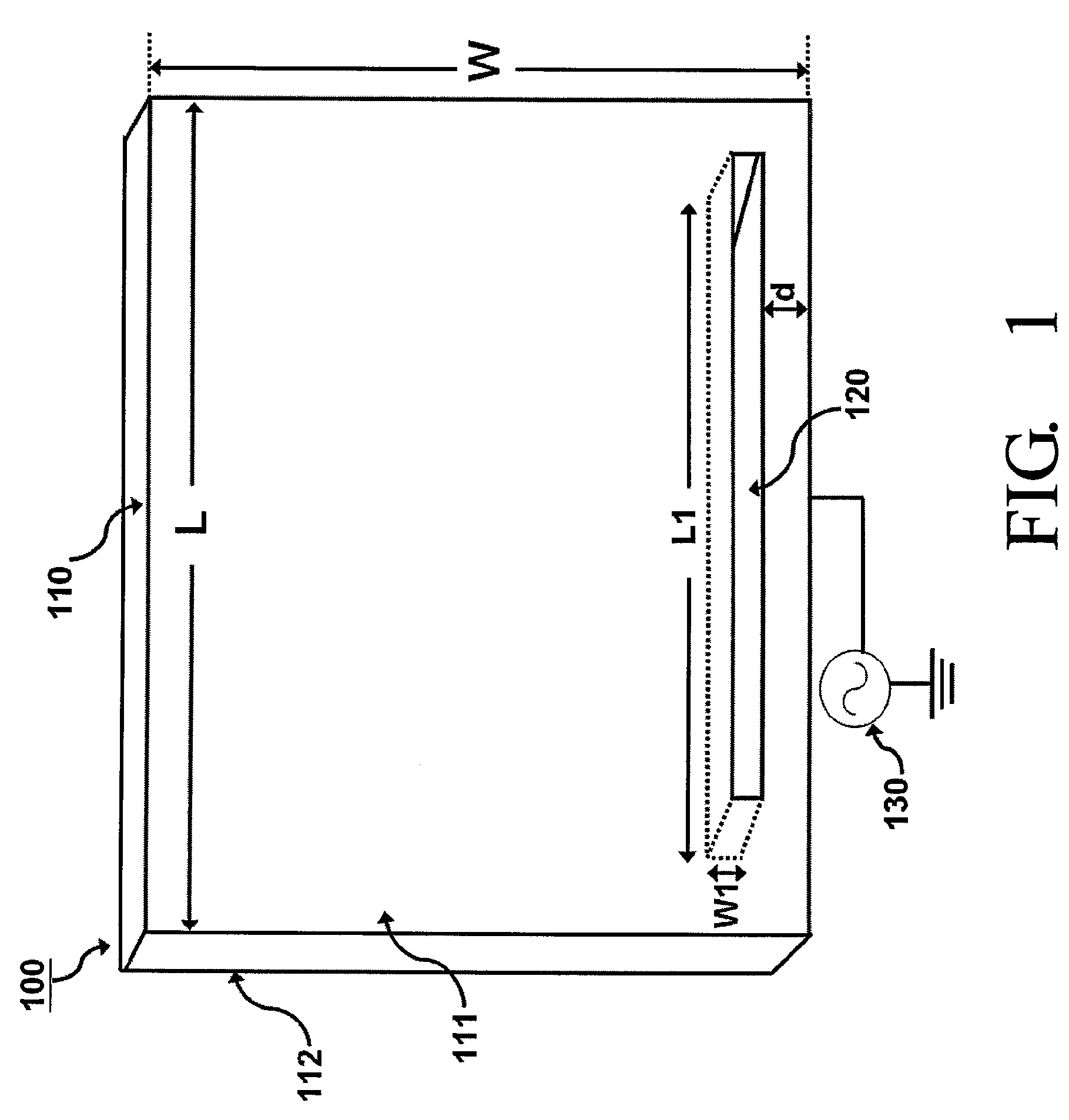
[0025]Referring FIG. 1, FIG. 1 is a schematic diagram illustrating the structure of an electrode 100 with improved plasma uniformity according to an embodiment of the present invention. According to the present embodiment, the electrode 100 comprises an electrode plate 110, a perturbation slot segment 120. The electrode plate 110 has a first surface 111 and a second surface 112 opposite to the first surface 111, and the electrode plate 110 is electrically connected to a RF current source 130 for generating an electric field. The perturbation slot segment 120 is adjacent to a side of the electrode plate 110. An etching process can be used to form the perturbation slot segment 120 symmetrically from th...


PUM

PropertyMeasurementUnit
frequencyaaaaaaaaaa
frequencyaaaaaaaaaa
impedanceaaaaaaaaaa

Abstract

An electrode with improved plasma uniformity is disclosed, which is used for a chamber capable of generating a plasma. The electrode comprises an electrode plate and a perturbation slot. By well designing the perturbation slot of the electrode, the disclosed electrode can improve the uniformity of the plasma density, and is suitable for use in various types of substrate and can be widely applied in a plasma process system.

Description

RELATED APPLICATIONS[0001]This application claims priority to Taiwan Application Serial Number 97201210, filed Jan. 18, 2008, which is herein incorporated by reference.BACKGROUND[0002]1. Field of Invention[0003]The present invention relates to an electrode, and more particularly, to an electrode plate with adjustable electric filed distribution for use in a plasma process apparatus.[0004]2. Description of Related Art[0005]In the current semiconductor process technologies, plasma can be used for performing effective film processing and etching tasks such as plasma-assisted chemical vapor deposition, plasma-assisted etching and plasma polymerization, and those processing techniques are applied in various industries such as TFT (Thin Film Transistor) LCD (Liquid Crystal Display) factories, solar energy manufacturers and foundries. For example, In the process for fabricating a microcrystalline silicon thin-film solar cell, a plasma-enhanced chemical vapor deposition (PECVD) process is g...

Claims


Application Information

Patent Timeline
Patent Type & Authority Applications(United States)
IPC IPC(8): C23C16/509
CPCH01J37/32009H01J37/3255H01J37/32541H01J37/32082
Inventor HUANG, MING-HUNGYEH, KUNG-HSUYANG, CHENG-ANHO, CHIEN-LI
Owner CONTREL TECH CO LTD
Learn More