
Television signal splitter casing

Inactive Publication Date: 2009-07-16
SIGNAL CABLE SYST
View PDF5 Cites 1 Cited by
  • Summary
  • Abstract
  • Description
  • Claims
  • Application Information

AI Technical Summary

Benefits of technology

[0008]The main objective of the present invention is to provide a television signal splitter casing that can be used to split a signal for two or more connectors and prevents EMI.
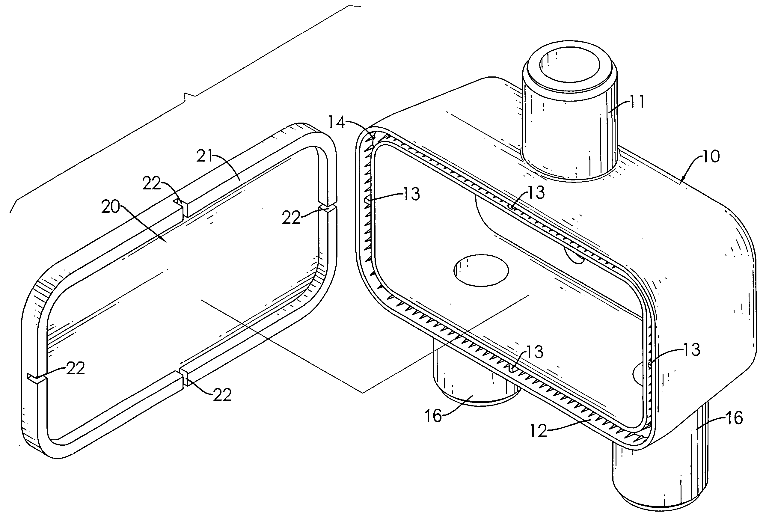
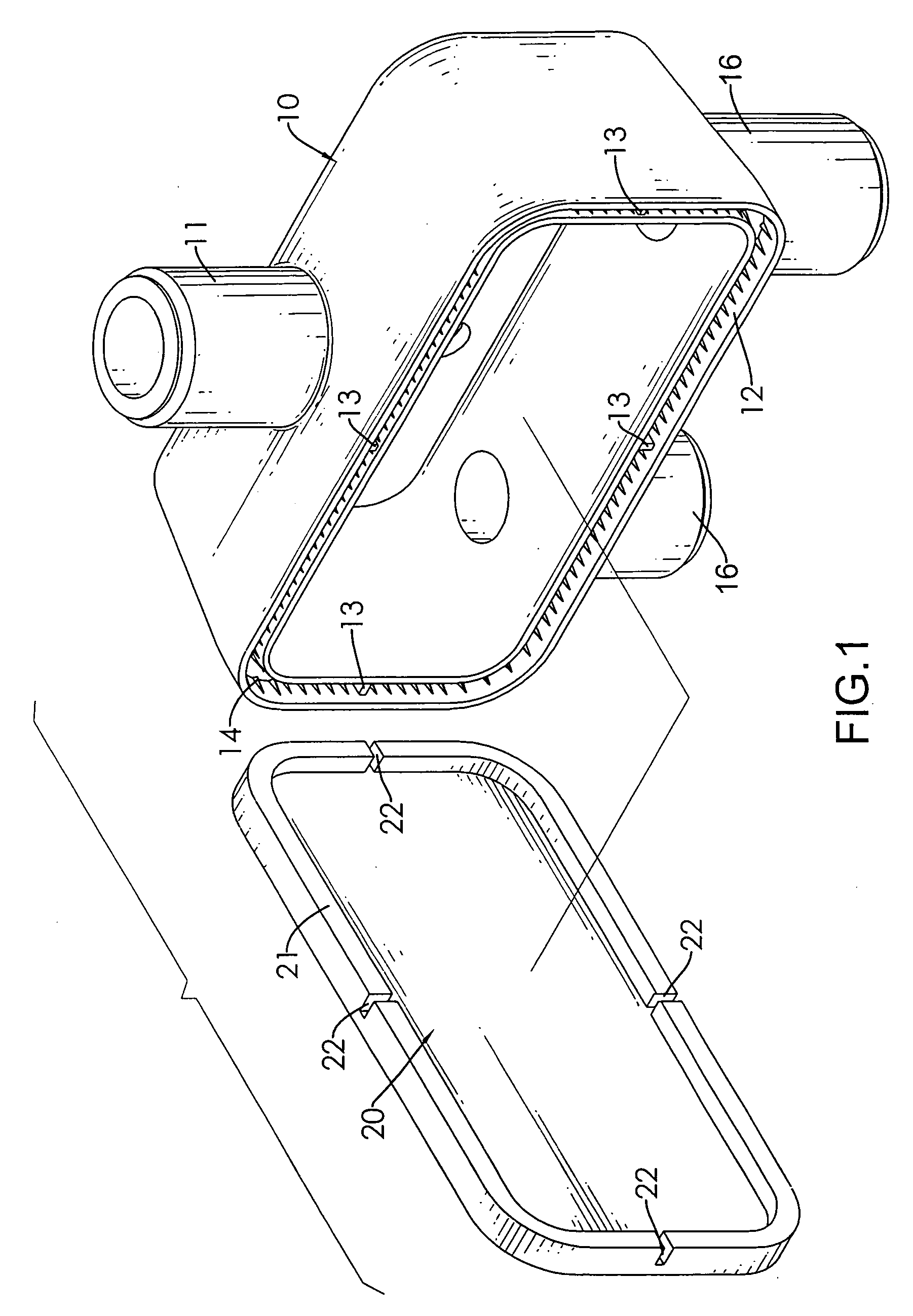
[0009]A television signal splitter casing in accordance with the present invention has a body and a cover. The body is hollow and has a front, an opening and a groove. The opening is defined in the front and has an annular edge. The groove is formed in the annular edge of the opening and has an inner surface and multiple saw-teeth. The saw-teeth are formed on the inner surface of the groove. The cover is mounted securely on the opening of the body and has a brim. The brim is mounted in the groove of the body. The saw-teeth of the groove tightly bite and securely hold the brim. Therefore, the cover is mounted on the body without any soldering process so that the fabricating cost of the television signal splitter casing is low.

Problems solved by technology

However, the fabricating cost of the television signal splitter is too high.
Although the fabricating cost of the conventional television signal splitter is lower, the engagement between the casing (82) and the cover (81) is not ideal.
The gaps of television signal splitter cause electromagnetic wave leakage interfering with nearby electronic devices.
However, the soldering process wastes time and has a high cost.

Method used


Image

  • Television signal splitter casing
  • Television signal splitter casing
  • Television signal splitter casing

Examples


Embodiment Construction

[0018]With reference to FIG. 1, a television signal splitter casing in accordance with the present invention comprises a body (10) and a cover (20).

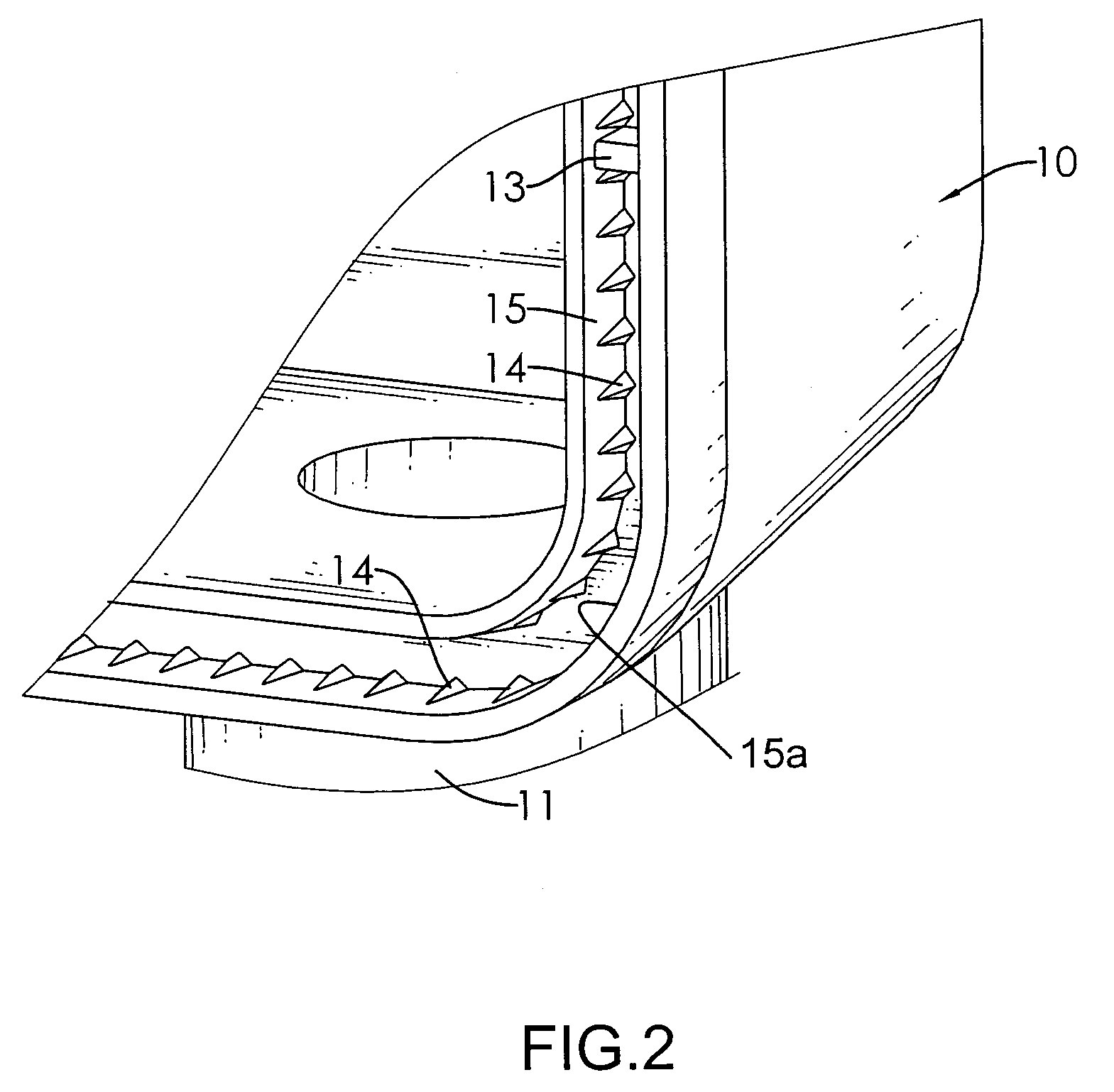
[0019]With reference to FIGS. 2 and 3, the body (10) is hollow and has a top, a bottom, a front, an opening, a cavity, an input connector (11), multiple output connectors (16) and a groove (12).

[0020]The opening is defined in the front and has an annular edge. The cavity is defined in the body (10) and communicates with the opening. The input connector (11) is formed on the top of the body (10). The output connectors (16) are formed on the bottom of the body (10). The groove (12) is annular and is formed in the annular edge of the opening and has an inner surface, multiple reinforcing tabs (13), multiple saw-teeth (14). The inner surface of the groove (12) has an annular inside surface (15) and an annular outside surface (15a) opposite to the annular inside surface (15). The reinforcing tabs (13) are formed transversely in the groove of ...


PUM


Abstract

A television signal splitter casing has a body and a cover. The body is hollow and has a front, an opening and a groove. The opening is defined in the front and has an annular edge. The groove is formed in the annular edge of the opening and has an inner surface and multiple saw-teeth. The saw-teeth are formed on the inner surface of the groove. The cover is mounted securely on the opening of the body and has a brim. The brim is mounted in the groove of the body. The saw-teeth of the groove tightly bite and securely hold the brim. Therefore, the cover is mounted on the body without any soldering process so that the fabricating cost of the television signal splitter casing is low.

Description

BACKGROUND OF THE INVENTION[0001]1. Field of the Invention[0002]The present invention relates to a splitter casing, especially to be a television signal splitter casing that prevents electromagnetic interference (EMI) with nearby electronic devices.[0003]2. Description of the Prior Arts[0004]A television signal splitter is used to split a signal for two or more connectors so that televisions connected respectively to the connectors are able to receive the same signal simultaneously. With reference to FIG. 5, a conventional television signal splitter comprises a cover (91) and a casing (92). The cover (91) has a brim (93) and a slot (931). The slot (931) is formed in the brim (93) of the cover (91). The casing (92) has an opening and a mounting protrusion (94). The mounting protrusion (94) is formed around the opening of the casing (92) and engages the slot (931) of the cover (91). However, the fabricating cost of the television signal splitter is too high.[0005]With reference to FIG...

Claims


Application Information

Patent Timeline
IPC IPC(8): H05K5/00
CPCH05K5/0004
Inventor CHUNG, JUI-HUANG
Owner SIGNAL CABLE SYST
Learn More