
Pressure Activated Valve with Angled Slit

a technology of pressure actuator and slit, which is applied in the direction of functional valve types, catheters, transportation and packaging, etc., can solve the problems of weakening the catheter wall, increasing the risk of infection and/or blood coagulation, and repeated and prolonged access to the vascular system of medical procedures

Inactive Publication Date: 2009-07-09
NAVILYST MEDICAL
View PDF3 Cites 22 Cited by
  • Summary
  • Abstract
  • Description
  • Claims
  • Application Information

AI Technical Summary

Benefits of technology

"The present invention is about a valve that opens when there is a certain level of pressure applied to it. It has a membrane with a slit that is closed when there is no pressure, but when there is pressure, the slit separates and allows fluid to flow through the membrane."

Problems solved by technology

Medical procedures often require repeated and prolonged access to the vascular system.
However, the repeated application of such clamps may weaken catheter walls as stress is repeatedly applied to the same locations on the catheter walls.
In addition, this clamping may result in an imperfect seal allowing air or other contaminants to enter the catheter entailing a risk of infection and / or coagulation of the blood.

Method used


Image

  • Pressure Activated Valve with Angled Slit
  • Pressure Activated Valve with Angled Slit
  • Pressure Activated Valve with Angled Slit

Examples


Embodiment Construction

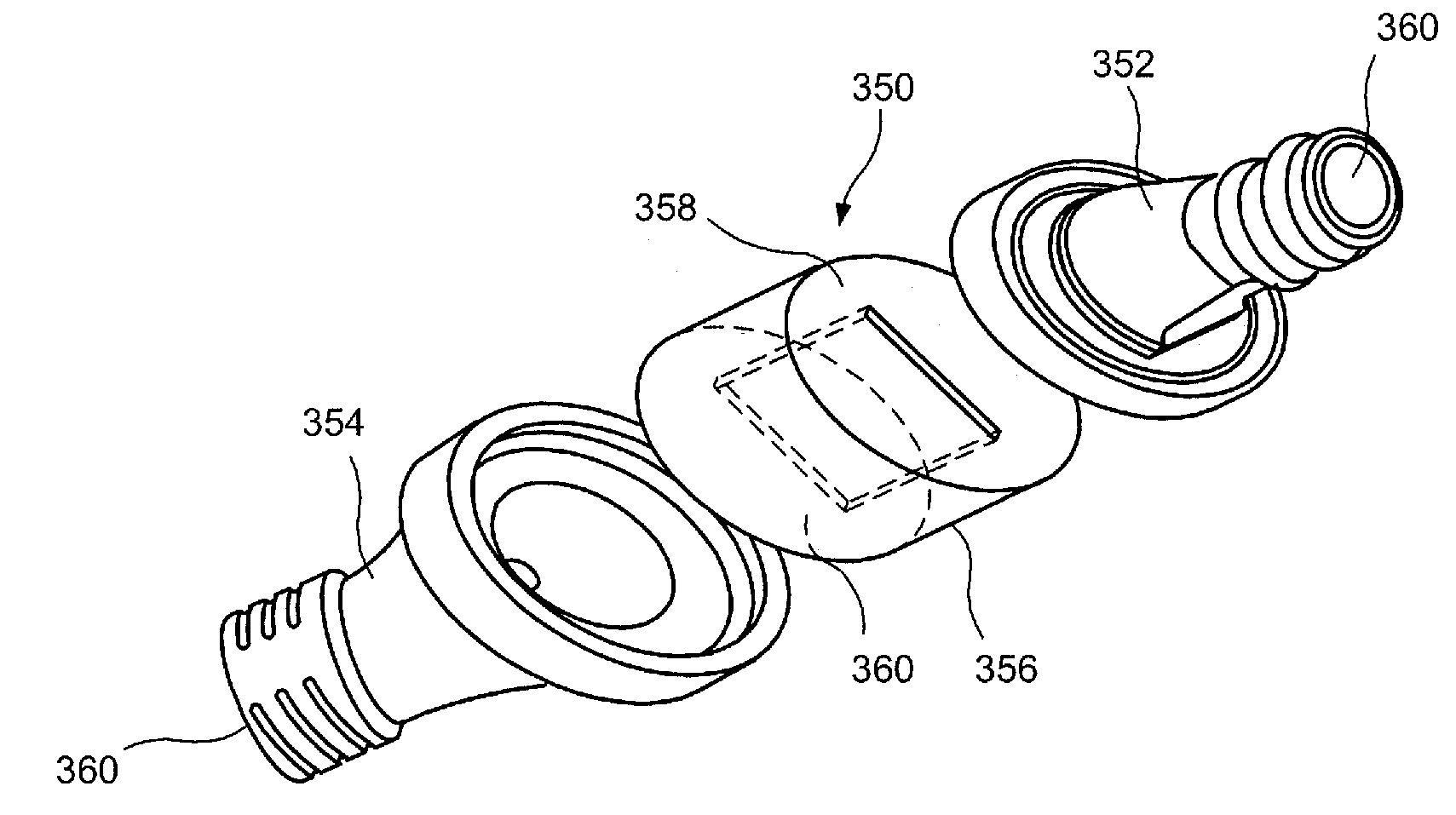
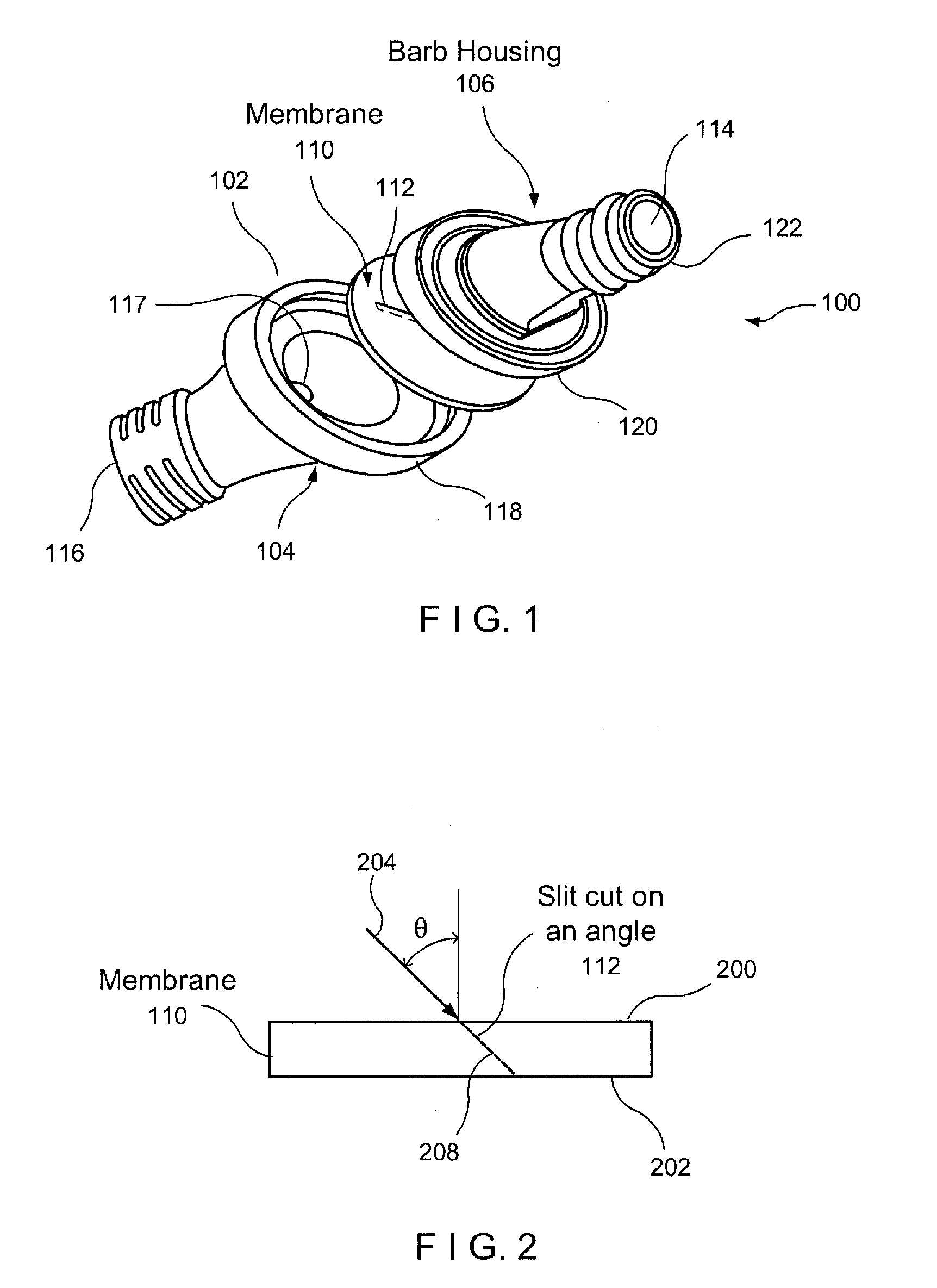
[0017]The present invention may be further understood with reference to the following description and the appended drawings, wherein like elements are referred to with the same reference numerals. The present invention is related to devices for accessing the vascular system and, in particular, to pressure activated valves sealing catheters facilitating chronic access to a blood vessel. Typical pressure activated valves comprises two principal components: 1) a valve housing an end of which is coupled to the catheter while the other end is coupled to an external device; and 2) a slitted membrane sandwiched between male and female halves of the housing.

[0018]Pressure activated valves automatically seal catheters as they are biased closed (e.g., by elastic properties of the material of the membrane) so that edges of the slit are moved apart from one another to permit fluid flow therethrough only when a fluid pressure applied thereto exceeds a predetermined threshold level. For example, ...


PUM


Abstract

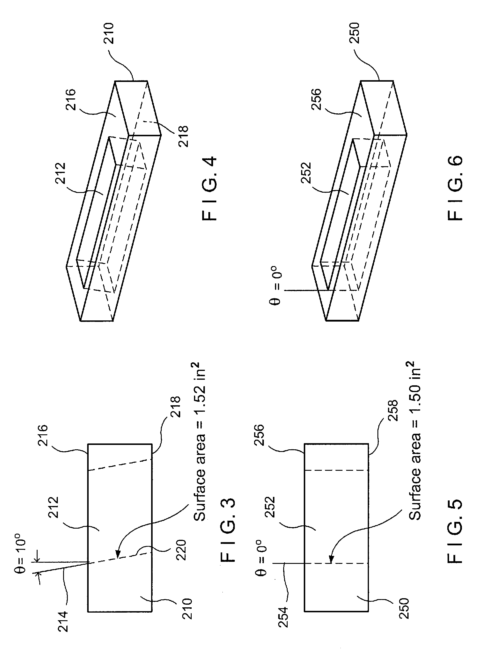
A pressure actuated valve comprises a first membrane having a slit extending through the membrane at a nonzero draft angle relative to a perpendicular to a surface of the membrane, material of the membrane biasing the slit closed so that the slit remains closed when a fluid pressure applied to the membrane is below a threshold level and, when the fluid pressure is at least the threshold level, edges of the slit separate from one another to permit fluid flow through the membrane.

Description

PRIORITY CLAIM[0001]The present application claims priority to U.S. Provisional Patent Application Ser. No. 60 / 971,356 filed on Sep. 11, 2007 entitled “Pressure Activated Valve With Angled Slit.” The entire disclosure of this application is expressly incorporated herein by reference.BACKGROUND OF THE INVENTION[0002]Medical procedures often require repeated and prolonged access to the vascular system. For example, a dialysis catheter may be implanted to form a semi-permanent conduit to and from a blood vessel for the removal and / or introduction of blood, fluids, medications, chemotherapy agents, nutrients, etc. The catheter must be sealed from the outside environment when not in use to prevent the leakage of fluids therefrom and to prevent external contaminants and air from entering the body.[0003]These catheters are often sealed between therapeutic sessions by applying clamps thereto. However, the repeated application of such clamps may weaken catheter walls as stress is repeatedly ...

Claims


Application Information

Patent Timeline
Patent Type & Authority Applications(United States)
IPC IPC(8): A61M25/14F16K15/14
CPCA61M39/24F16K15/147A61M2039/2426A61M2039/242Y10T137/7881
Inventor WEAVER QUIGLEY, KARLAGRANTZ, STEVENPOK, RICHARDHIEN, ANTHONYUN, KIMBERLY
Owner NAVILYST MEDICAL
Learn More