
Non-blood contact cardiac compression device, for augmentation of cardiac function by timed cyclic tensioning of elastic cords in an epicardial location

a compression device and non-blood contact technology, applied in the field of physical devices for the treatment of human heart failure, can solve problems such as external compression of the heart, and achieve the effects of reducing the internal volume of the cardiac ventricles, enhancing the natural cardiac contraction, and enhancing the pumping function of the hear

Inactive Publication Date: 2009-07-09
WHITE ANTHONY JOHN
View PDF60 Cites 17 Cited by
  • Summary
  • Abstract
  • Description
  • Claims
  • Application Information

AI Technical Summary

Benefits of technology

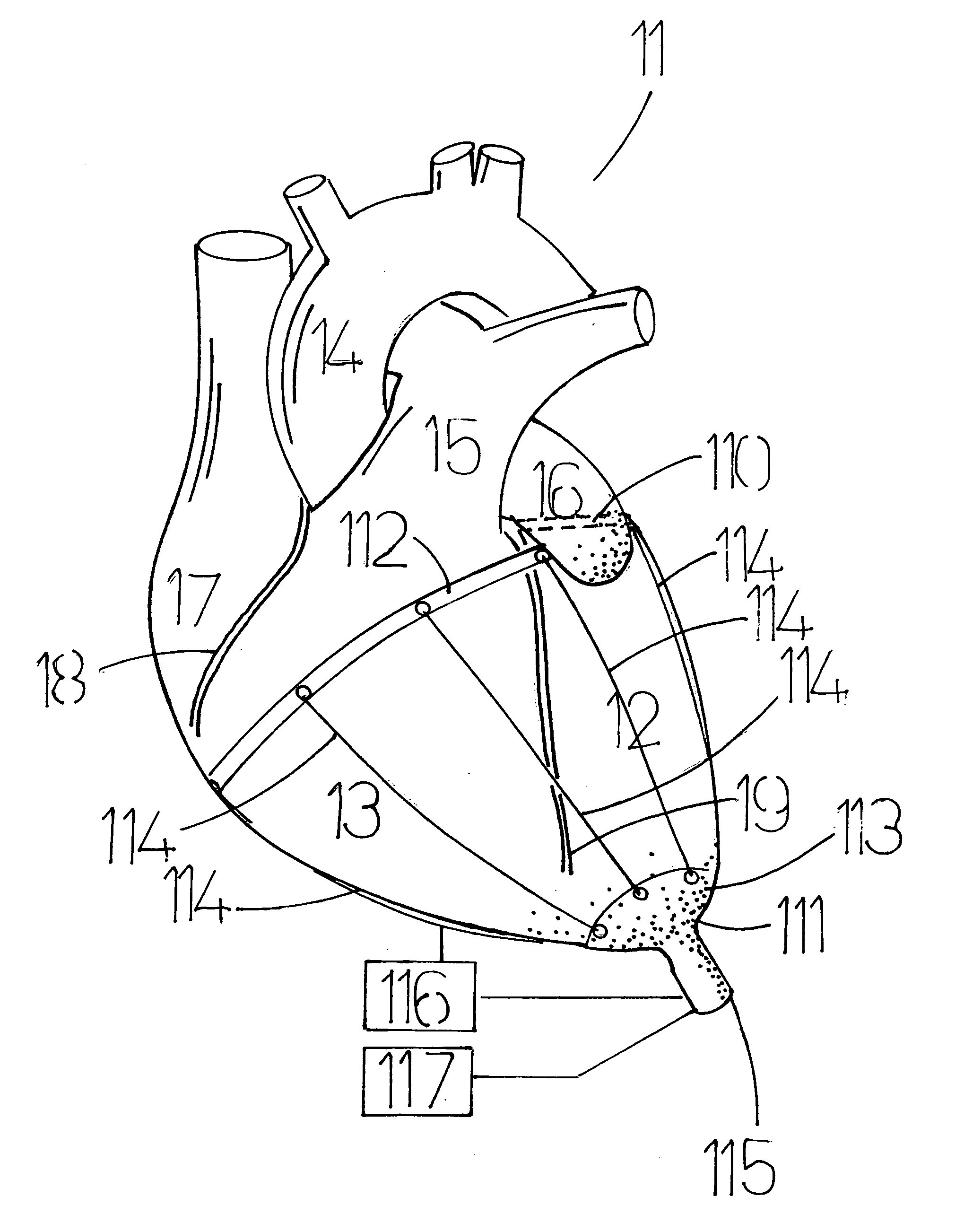
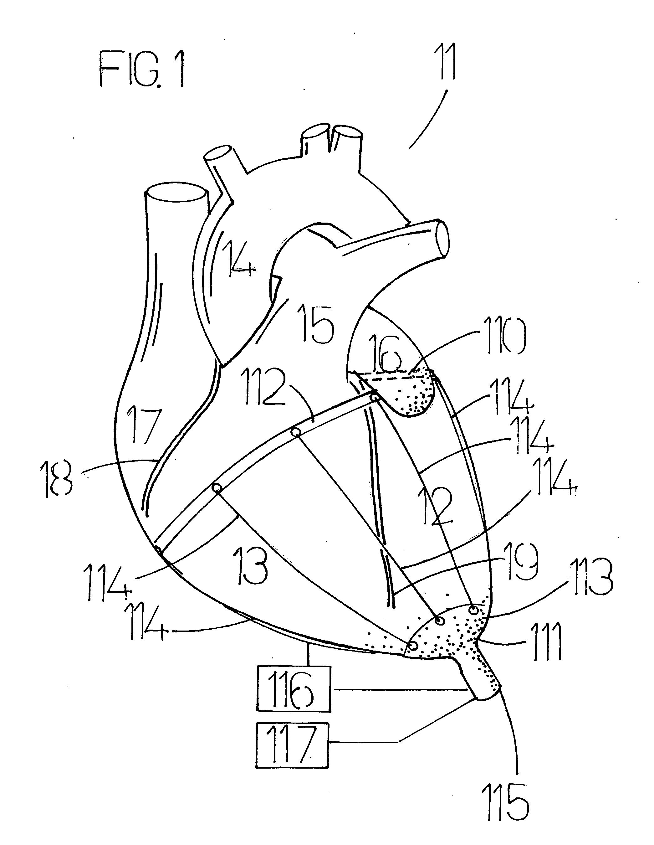
[0062]This embodiment addresses the objective of augmenting the pumping function of the heart by means of connectors with elastic properties, positioned immediately proximate to the outer surface of the heart. Each of the elastic connectors is attached at one end to a circumferential band firmly attached to the heart, and at the other end to a component attached firmly to the heart at the anatomical apex of the heart. A mechanism exists to place the elastic connectors alternatively unde

Problems solved by technology

When the elastic connectors are stretched they will have the natural characteristic to draw the apex and circumferential band together, resulting in external compression of the heart.

Method used


Image

  • Non-blood contact cardiac compression device, for augmentation of cardiac function by timed cyclic tensioning of elastic cords in an epicardial location
  • Non-blood contact cardiac compression device, for augmentation of cardiac function by timed cyclic tensioning of elastic cords in an epicardial location
  • Non-blood contact cardiac compression device, for augmentation of cardiac function by timed cyclic tensioning of elastic cords in an epicardial location

Examples


Embodiment Construction

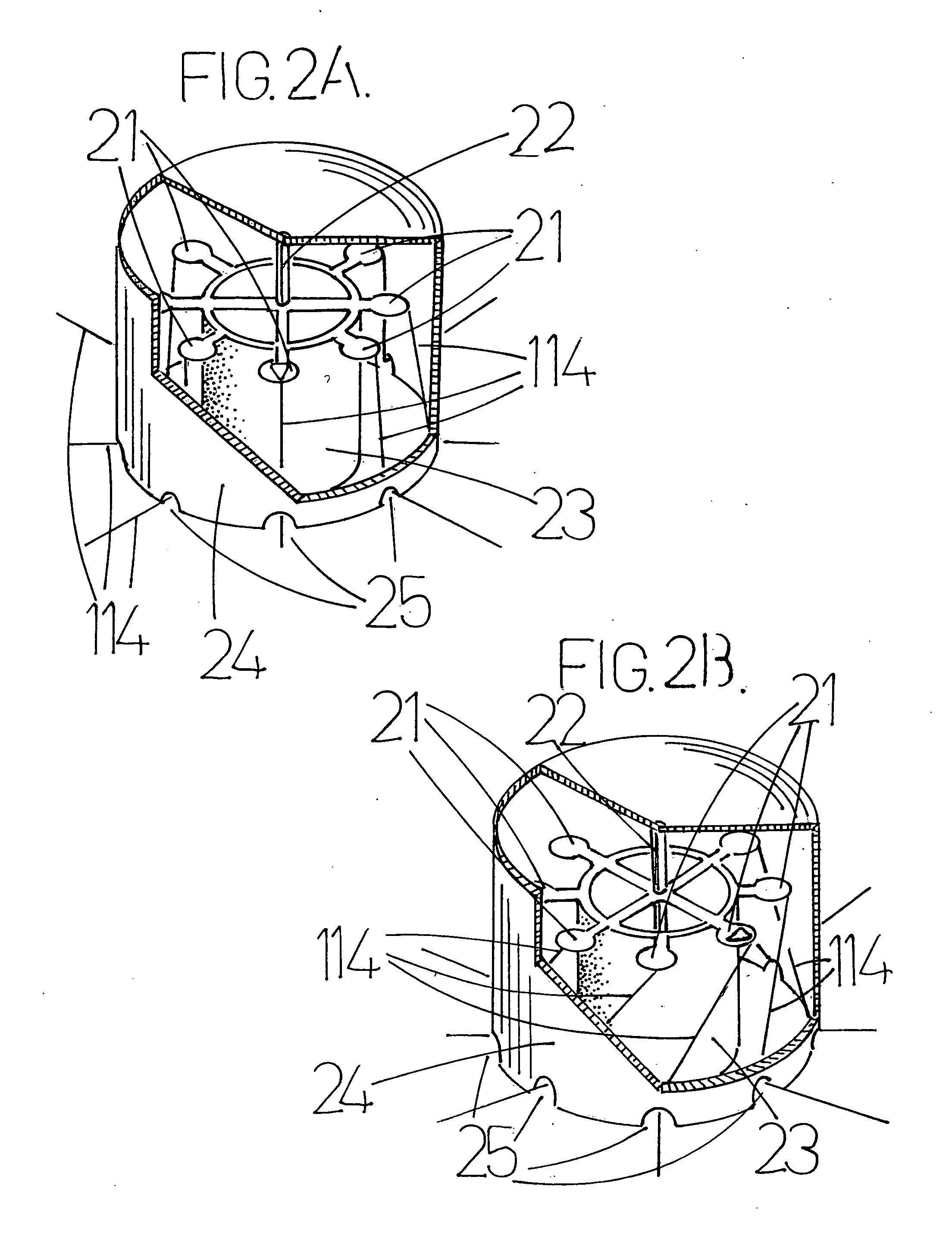
[0119]This embodiment augments the pumping function of the heart. One component of the embodiment is a set of 5 or more connectors with elastic properties, located immediately proximate to the outer surface of the heart. Each of the elastic connectors is attached at one end to a circumferential band firmly attached to the heart, and at the other end to a component attached firmly to the heart at the anatomical apex of the heart. A mechanism exists to place the elastic connectors alternatively under tension (stretch) then being allowed to elongate (relax). When the elastic connectors are stretched they will have the action of drawing the apex and circumferential band together because the connectors are attached to said two components at either end. This results in external compression of the heart. This movement will cause the internal volume of the cardiac ventricles to be reduced, thereby encouraging expulsion of the blood contents of the ventricles to be expelled. This compressive...


PUM


Abstract

One embodiment of a device to augment the pumping function of a weakened heart. A set of connectors with elastic properties are positioned immediately proximate to the outer surface of the heart. Each of the elastic connectors is attached at one end to a circumferential band firmly attached to the exterior surface of the heart at around the level of the atrioventricular groove, an anatomical feature of the heart. At the other end, each of said elastic connectors is attached to a cap attached firmly to the heart exterior of the heart at the anatomical apex. A mechanism places the elastic connectors alternatively under tension (stretch) then shortening (relaxation). When the elastic connectors are stretched they draw the apex and circumferential band together, resulting in external compression of the heart. This movement causes the internal volume of the cardiac ventricles to be reduced, thereby encouraging expulsion of the blood contents of the ventricles to be expelled. This action will be timed so as to augment the natural cardiac contraction, and thereby improve its pumping function.

Description

FIELD OF THE INVENTION[0001]This invention generally relates to physical devices for the treatment of human heart failure, and more specifically to assisting the natural heart's function by intermittent stretching of a number of longitudinal elastic fibres positioned in immediate proximity to the external surface of the heart, carefully timed to the heart's natural beating.BACKGROUND OF THE FIELD[0002]Heart failure is also commonly referred to as congestive cardiac failure (CCF). This is a common clinical syndrome, in which the cardiac output (measured in liters per minute) is inadequate to provide enough blood flow to the body's tissues to meet their demand for oxygen and nutrients.[0003]There are many causes of cardiac failure, the commonest of which are hypertension, coronary artery disease and dilated cardiomyopathy (the last of these categories is an intrinsic weakness of heart muscle contraction). Another broad way to sub-divide cardiac failure is as systolic heart failure (we...

Claims


Application Information

Patent Timeline
IPC IPC(8): A61F2/02A61M60/191A61M60/268A61M60/438
CPCA61F2/2481A61M1/1046A61M2205/8206A61M2230/06A61M1/1068A61M60/268A61M60/438A61M60/191
Inventor WHITE, ANTHONY JOHN
Owner WHITE ANTHONY JOHN
Learn More