
Illumination device, image display device, and projector

a technology of image display and projection device, which is applied in the direction of instruments, projectors, optics, etc., can solve the problems of difficult illumination of the illuminated region, difficult difficult to make the light intensity distribution uniform, etc., to achieve good light intensity distribution, simple and compact projection device, and high light use efficiency

Active Publication Date: 2009-07-09
SEIKO EPSON CORP
View PDF5 Cites 15 Cited by
  • Summary
  • Abstract
  • Description
  • Claims
  • Application Information

AI Technical Summary

Benefits of technology

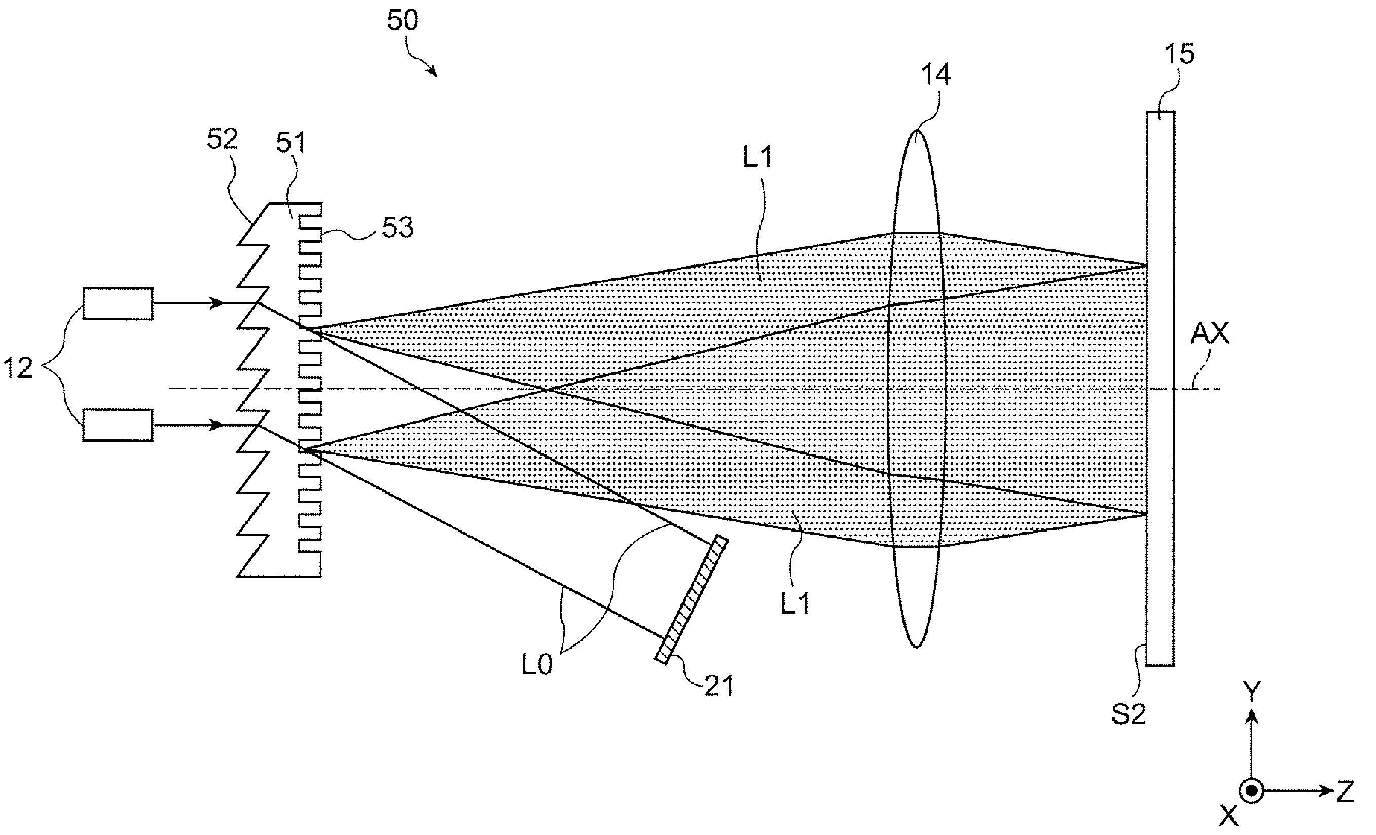
The invention provides an illumination device that can easily achieve shaping of the illuminated region and uniform light intensity distribution. The device includes a light source unit that emits coherent light and a diffractive optical element that diffracts the coherent light. The diffractive optical element is designed to have a zero-order light component travel in a direction inclined with respect to a perpendicular line of reference. By making the zero-order light components travel in a direction inclined with respect to the perpendicular line of reference, an angle formed by the beam line of the zero-order light and the principal beam of the diffracted light can be made small. This allows for easy shaping of the illuminated region and uniform light intensity distribution. The device also includes a collimating lens that collimates the diffracted light components from the diffractive optical element to travel to the illuminated surface. The use of multiple light source units and a plurality of diffractive optical elements can further improve the bright light supply and light use efficiency.

Problems solved by technology

Since only a part of the illuminated region is bright, it becomes difficult to obtain good light intensity distribution.
For this reason, a problem that shaping of the illuminated region and making the light intensity distribution uniform may be difficult occurs in the related art.

Method used


Image

  • Illumination device, image display device, and projector
  • Illumination device, image display device, and projector
  • Illumination device, image display device, and projector

Examples


first embodiment

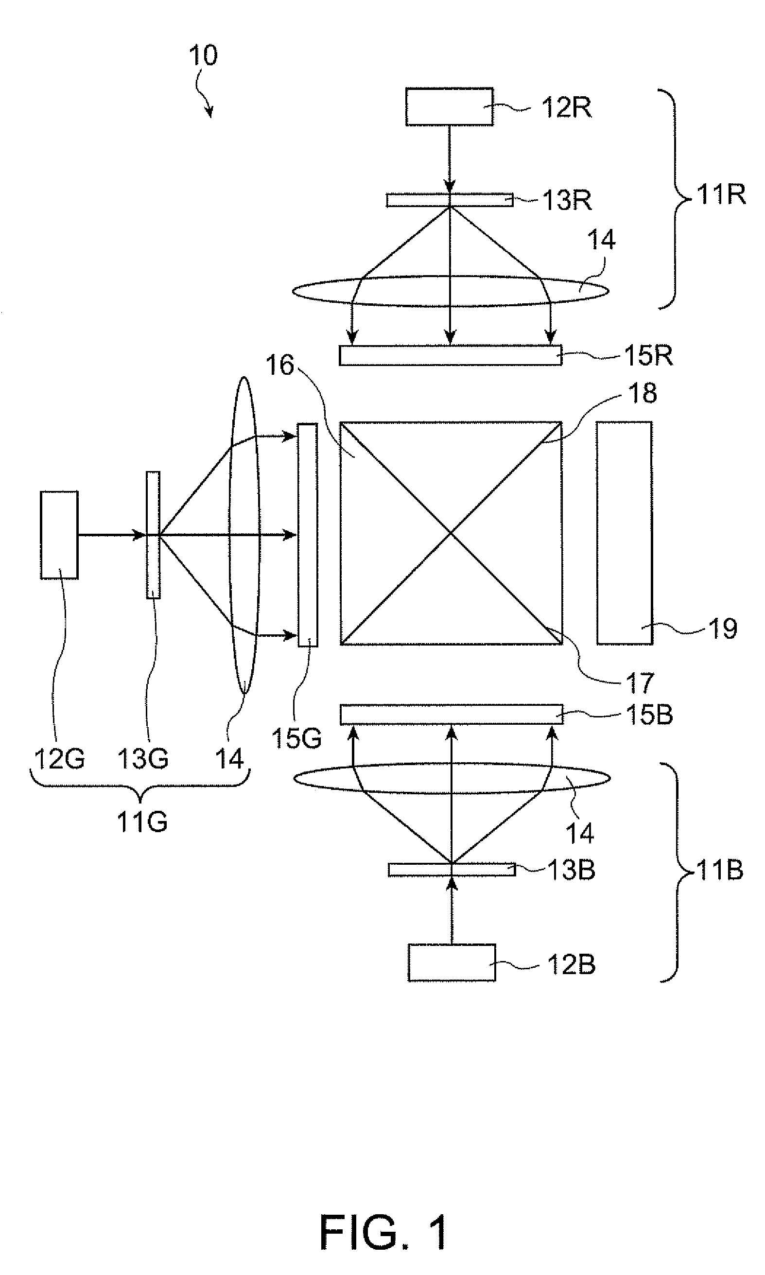
[0048]FIG. 1 is a top view schematically illustrating the configuration of a projector 10 according to a first embodiment of the invention. The projector 10 is a front projection type projector that projects light onto a screen (not shown) and makes the light reflected from the screen observed so that a viewer enjoys an image. The projector 10 has a first illumination device 11R, a second illumination device 11G, and a third illumination device 11B. The first illumination device 11R is an illumination device that supplies red (R) light, which is a first color light component. The second illumination device 11G is an illumination device that supplies green (G) light, which is a second color light component. The third illumination device 11B is an illumination device that supplies blue (B) light, which is a third color light component. The projector 10 is an image display device that displays an image using R light supplied from the first illumination device 11R, G light supplied from...

second embodiment

[0076]FIG. 12 is a side view schematically illustrating the configuration of an illumination device 30 according to a second embodiment of the invention. The illumination device 30 according to the present embodiment may be applied to the projector 10 according to the first embodiment. The same components as in the above-described embodiment are denoted by the same reference numerals, and a repeated explanation will be omitted. The illumination device 30 according to the present embodiment has three laser light sources 12. Each of the laser light sources 12 is a light source unit that emits a laser beam which is coherent light. The three laser light sources 12 are arrayed in parallel in the Y-axis direction. Each of the laser light sources 12 makes a laser beam travel in a state where the laser beam is inclined with respect to the perpendicular line N of the incidence surface S1, which is a reference plane on which a diffractive optical element 31 is disposed. The laser beams emitte...

third embodiment

[0081]FIG. 13 is a side view schematically illustrating the configuration of an illumination device 33 according to a third embodiment of the invention. The illumination device 33 according to the present embodiment may be applied to the projector 10 according to the first embodiment. While laser beams are made to travel approximately in parallel from the plurality of laser light sources in the second embodiment, laser beams are made to travel in different directions from a plurality of laser light sources in the present embodiment. The same components as in the above-described embodiment are denoted by the same reference numerals, and a repeated explanation will be omitted. The illumination device 33 according to the present embodiment has a first laser light source 12a and a second laser light source 12b. The first laser Light source 12a and the second laser light source 12b are light source units that emit a laser beam which is coherent light. The first laser light source 12a and...


PUM


Abstract

An illumination device includes: a light source unit that emits coherent light; and a diffractive optical element that diffracts the coherent light emitted from the light source unit and makes the diffracted light travel to an illuminated surface. The diffractive optical element is disposed such that the coherent light is incident in a state of being inclined with respect to a perpendicular line of a reference plane on which the diffractive optical element is disposed. Zero-order light, which is light other than the diffracted light, of light components emitted from the diffractive optical element travels to a position other than the illuminated surface.

Description

BACKGROUND[0001]1. Technical Field[0002]The present invention relates to an illumination device, an image display device, and a projector and in particular, to a technique of an illumination device using a laser light source.[0003]2. Related Art[0004]In recent years, a technique of using a laser light source as an illumination device of a projector has been proposed. For example, a diffractive optical element may be used as an overlapping unit that makes laser beams overlap on an illuminated surface. The diffractive optical element performs shaping and enlargement of an illuminated region and makes the light intensity distribution in the illuminated region uniform by diffracting a laser beam which is coherent light. By realizing a plurality of functions with the diffractive optical element, the illumination device can be made with a small number of components. As a result, it becomes easy to make the illumination device small and to save the space. When zero-order light and diffract...

Claims


Application Information

Patent Timeline
Patent Type & Authority Applications(United States)
IPC IPC(8): G02B27/42
CPCG03B21/208G03B21/2033
Inventor TAKAGI, MASAYUKITAKEDA, TAKASHIYAMAUCHI, TAISUKE
Owner SEIKO EPSON CORP
Learn More