Network-controlled charging system for electric vehicles
a charging system and electric vehicle technology, applied in the integration of power network operation systems, wireless communication, and arrangements for several simultaneous batteries, etc., can solve the problems of low demand, limited use of electric vehicles, and inefficient recharging of batteries that typically requires hours
- Summary
- Abstract
- Description
- Claims
- Application Information
AI Technical Summary
Benefits of technology
Problems solved by technology
Method used
Image
Examples
first embodiment
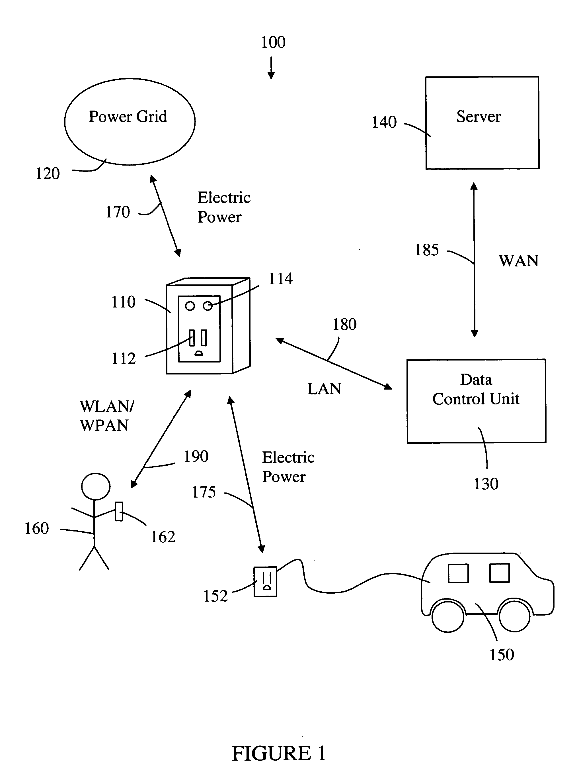
[0035]the network-controlled charge transfer system 100 for charging electric vehicles is shown in FIG. 1. The system 100 comprises a network-controlled charge transfer device 110, a local power grid 120, a data control unit 130, and a server 140. The system 100 interfaces with an electric vehicle 150, with an electrical connector 152, and an electric vehicle operator 160, via a mobile communication device 162. The network-controlled charge transfer device 110, referred to herein as a Smartlet™, is connected to the local power grid 120 by an electric power line 170, and to the electric vehicle 150 by the electrical connector 152. The flow of electrical power may be in either direction for both of these electrical connections. In other words, the electric vehicle 150 can be recharged from the local power grid 120, or the local power grid 120 can receive power from the electric vehicle 150. The Smartlet™110 has a communication link to the data control unit 130 over a local area networ...
second embodiment
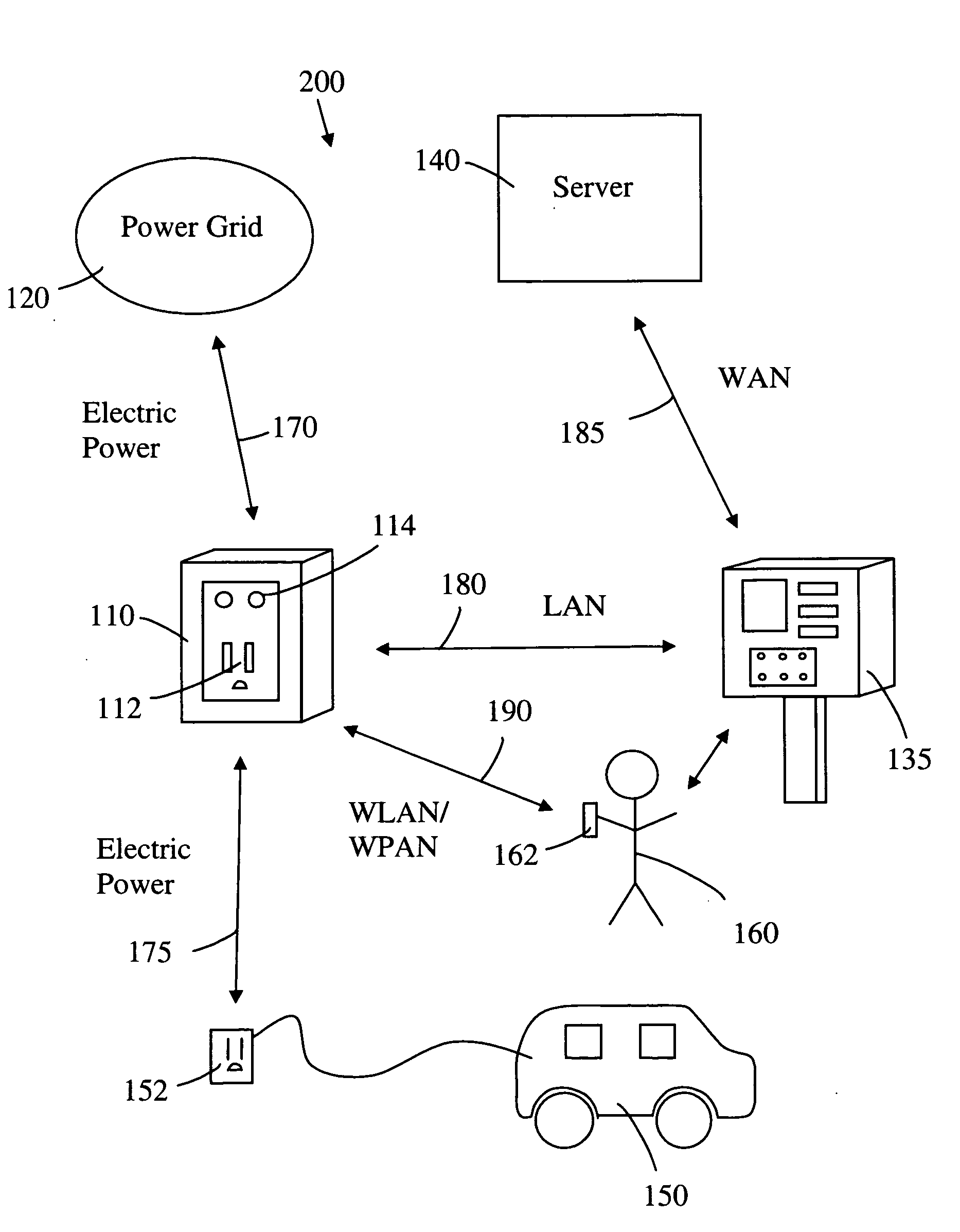
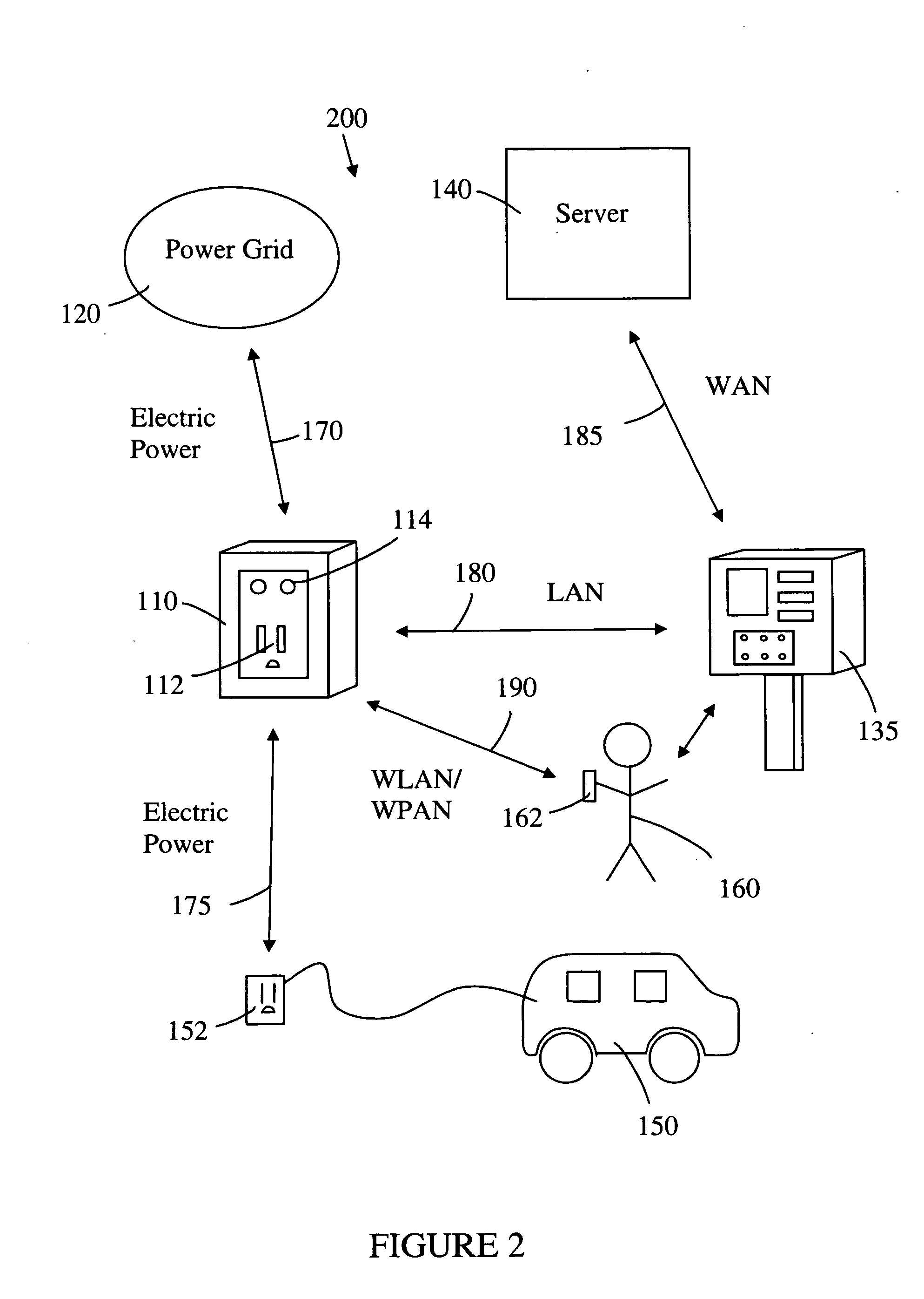
[0043]the network controlled charge transfer system 200 for charging electric vehicles 150 is shown in FIG. 2. The system 200 comprises a network-controlled charge transfer device (Smartlet™110, a local power grid 120, a payment station 135, and a server 140. The system 200 interfaces with an electric vehicle 150, with an electrical connector 152, and an electric vehicle operator 160, via a mobile communication device 162. The Smartlet™110 is connected to the local power grid 120 by an electric power line 170, and to the electric vehicle 150 by the electrical connector 152. The flow of electrical power may be in either direction for both of these electrical connections. The Smartlet™110 has a communication link to the payment station 135 over a LAN 180. The LAN 180 may be either a WLAN or a PLC network. The payment station 135 has a communication link to the server 140 over a WAN 185. (In this embodiment, the payment station 135 is taking the place of the data control unit 130 for a...
PUM
 Abstract
Description
Claims
Application Information
 - R&D
- Intellectual Property
- Life Sciences
- Materials
- Tech Scout
- Unparalleled Data Quality
- Higher Quality Content
- 60% Fewer Hallucinations
Browse by: Latest US Patents, China's latest patents, Technical Efficacy Thesaurus, Application Domain, Technology Topic, Popular Technical Reports.
© 2025 PatSnap. All rights reserved.Legal|Privacy policy|Modern Slavery Act Transparency Statement|Sitemap|About US| Contact US: help@patsnap.com


