Enhanced apparatus for percutaneous catheter implantation and replacement

a technology of percutaneous catheter and implantation device, which is applied in the field of medical technology, can solve the problems of difficult removal and/or repositioning of implanted catheters, difficulty in removing and/or repositioning catheters, and easy infection and inflammation at the catheter entry site, so as to avoid tissue injury, facilitate repositioning, and replace, and simplify implantation.

Active Publication Date: 2009-07-02
INCUMED LLC A NEVADA LIMITED LIABILITY +1
View PDF37 Cites 20 Cited by
  • Summary
  • Abstract
  • Description
  • Claims
  • Application Information

AI Technical Summary

Benefits of technology

[0006]The present invention is directed to an enhanced medical apparatus embodiment for more conveniently percutaneously implanting an elongate conduit, e.g., a catheter or cable, in a manner which both avoids tissue injury as the apparatus is implanted and allows the conduit to be easily positioned, repositioned, and replaced. The apparatus includes an elongate tubular sleeve having a forward portion whose outer surface is tapered to dilate a patient's skin incision as the sleeve is inserted therethrough. The sleeve includes an interior axial passageway through which the conduit is able to slide.
[0008]The aforedescribed configuration permits the sleeve to be implanted through a single minimally sized incision while avoiding injury to incision adjacent tissue which might otherwise be caused as the porous material passes through the incision. More particularly, it is preferable to provide an intentionally undersized incision (i.e., approximately 10-20% smaller than D4) for receiving the sleeve distal end, as is taught in applicant's aforementioned parent application Ser. No. 12 / 287,130. In use, as the sleeve forward portion is inserted through the incision, the smooth tapered surface gently elastically stretches, or dilates, the patient's adjacent tissue to a diameter D2 allowing the porous material to pass through the incision without abrading or otherwise injuring the incision adjacent tissue.
[0009]The sleeve interior axial passageway is dimensioned to snugly accommodate the outer surface of a conduit (which will hereinafter be assumed to be a catheter unless otherwise stated) while permitting the conduit to slide and rotate in the passageway relative to the sleeve. A sealing device within the sleeve extends around the catheter, e.g., near the sleeve proximal end, to prevent deleterious material from migrating into the patient's body along the catheter outer surface. The sealing device preferably comprises an annular seal formed of a soft flexible material, e.g., silicone, mounted within the sleeve passageway. The annular seal comprises a peripheral wall having an outer surface and an inner surface surrounding an interior bore. At least one annular flexible nib on the seal inner surface projects radially into the bore for sealing against the catheter outer surface. Although the sleeve preferably comprises a rigid titanium tube, alternatively, the sleeve can be formed of flexible tubing, e.g., silicone, allowing an interior annular sealing nib to be formed integral therewith.
[0010]The preferred embodiment also includes a locking member hinged to the anchor device mounted near the sleeve proximal end. The locking member can be readily pivoted between a first, or locked, position surrounding the conduit and a second, or unlocked, position remote from the conduit. In the unlocked position, the catheter is able to slide and / or rotate relative to the sleeve passageway. In the locked position, the locking member is able to apply a friction force to the catheter outer surface to prevent relative movement between the catheter and the sleeve. A preferred locking member comprises a split ring formed of a soft flexible material, e.g., silicone which, in the locked position, can be radially compressed to frictionally grip the catheter outer surface to prevent catheter movement relative to the sleeve. The split ring can be compressed in various ways; e.g., by simply tying it with suture thread or by using an internal or external clip, e.g., spring urged clamp, to pinch the split ring.
[0011]In a preferred procedure, a physician will make a controlled incision having a width approximately 10-20% less than D4, near the patient's chest or abdomen. A surgical tunneler tool is then typically inserted through the incision, to form a subcutaneous tunnel to an interior site through which a standard flexible catheter can be inserted and positioned. In accordance with the invention, the catheter carries the aforementioned sleeve and functions to guide the sleeve distal end through the undersized incision to place the sleeve porous layer in contact with the patient's dermis beneath the patient's outer skin surface. The sleeve proximal end is then preferably externally anchored to the patient's skin. With the locking member in its unlocked position, the physician is able to slide and / or rotate the catheter relative to the sleeve and locking member for optimum catheter tip positioning. When the catheter is properly positioned, the physician can then pivot the locking member to the locked position and then compress it to grip the catheter outer surface. With the sleeve thus implanted, the patient's subcutaneous tissue will, over time, grow into the porous material to anchor the sleeve and form an infection resistant barrier. The porous material, and / or sleeve interior, can be coated or impregnated with constituents having antimicrobial and / or anti-inflammatory properties, e.g., silver containing compounds or antibiotic eluting coatings and / or steroids, to further promote healing.

Problems solved by technology

Unless adequate precautions are taken, infections and inflammation can readily occur at the catheter entry site.
Although such a cuff can reduce the likelihood of infection, once ingrown its presence increases the difficulty of removing and / or repositioning an implanted catheter.
More particularly, it is not uncommon for an implanted catheter to become damaged, e.g., clogged or kinked, over an extended period of use thus necessitating catheter removal and / or replacement.

Method used


Image

  • Enhanced apparatus for percutaneous catheter implantation and replacement
  • Enhanced apparatus for percutaneous catheter implantation and replacement
  • Enhanced apparatus for percutaneous catheter implantation and replacement

Examples


Embodiment Construction

[0027]Various medical regimens relating, for example, to hemodialysis drug infusion, plasmapheresis, etc., use a percutaneously implanted conduit for conveying fluid and / or electric signals to / from an interior body site. The present invention is directed to a method and apparatus for facilitating the implantation and utilization of a percutaneous conduit (e.g., catheter) and for facilitating the positioning, repositioning, and replacement, or exchange, of the catheter.

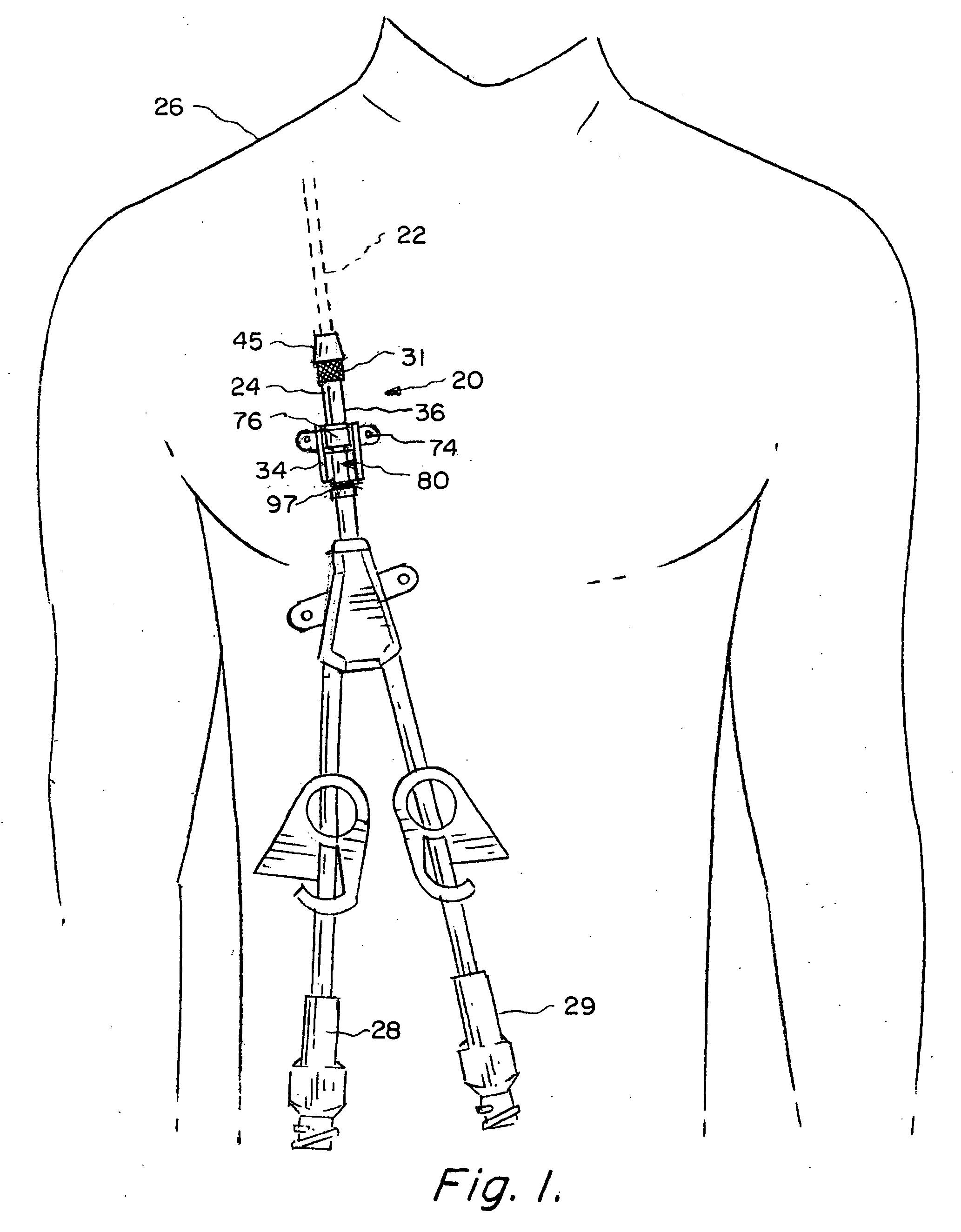
[0028]FIG. 1 schematically depicts an assembly 20 in accordance with the invention for percutaneously implanting a catheter 22 through an incision 24 in a patient 26 undergoing an exemplary hemodialysis procedure. In such a procedure, a dual lumen catheter 22 is typically used with the two lumens being respectively coupled to separate exterior flow couplers 28 and 29.

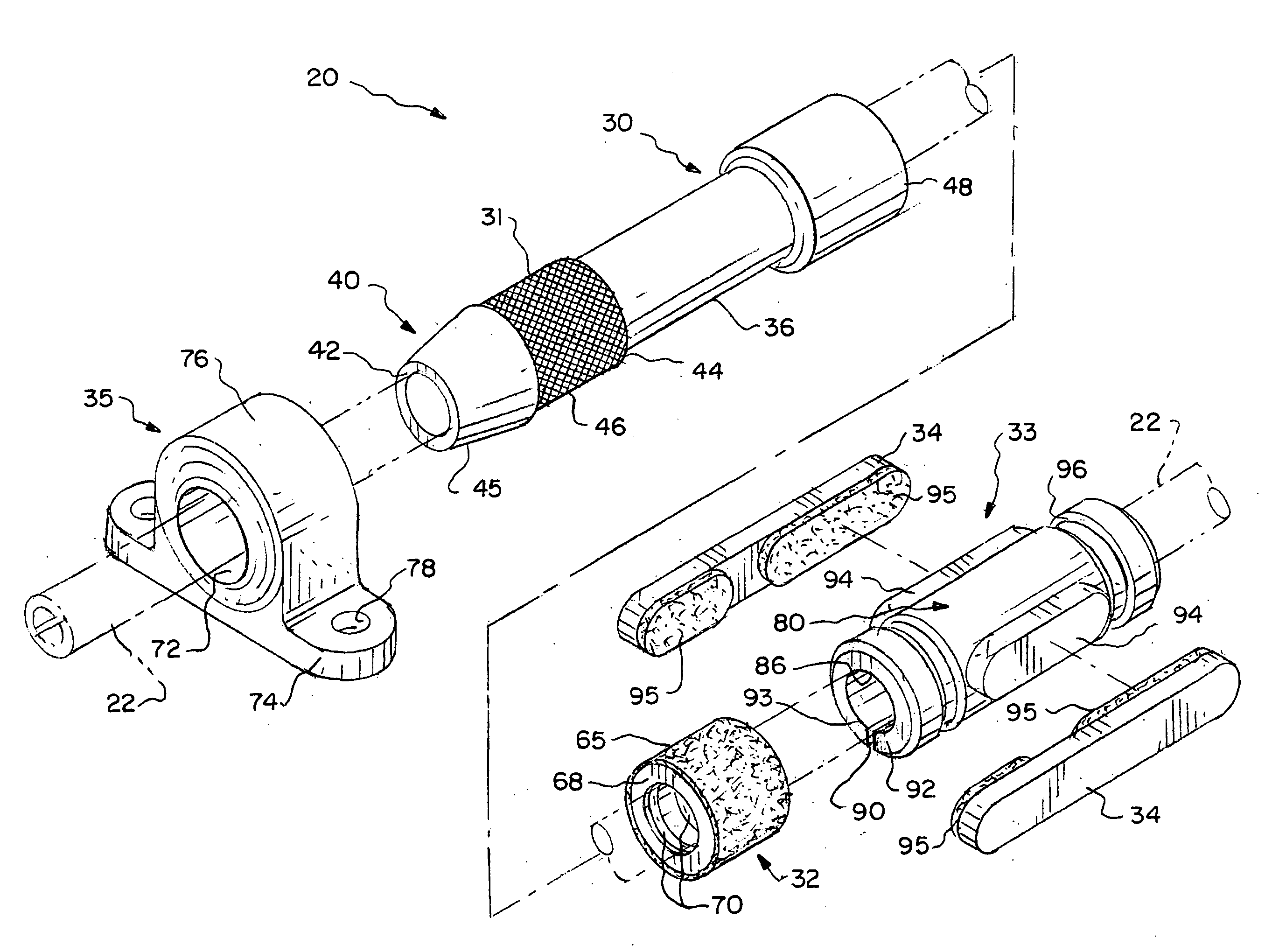
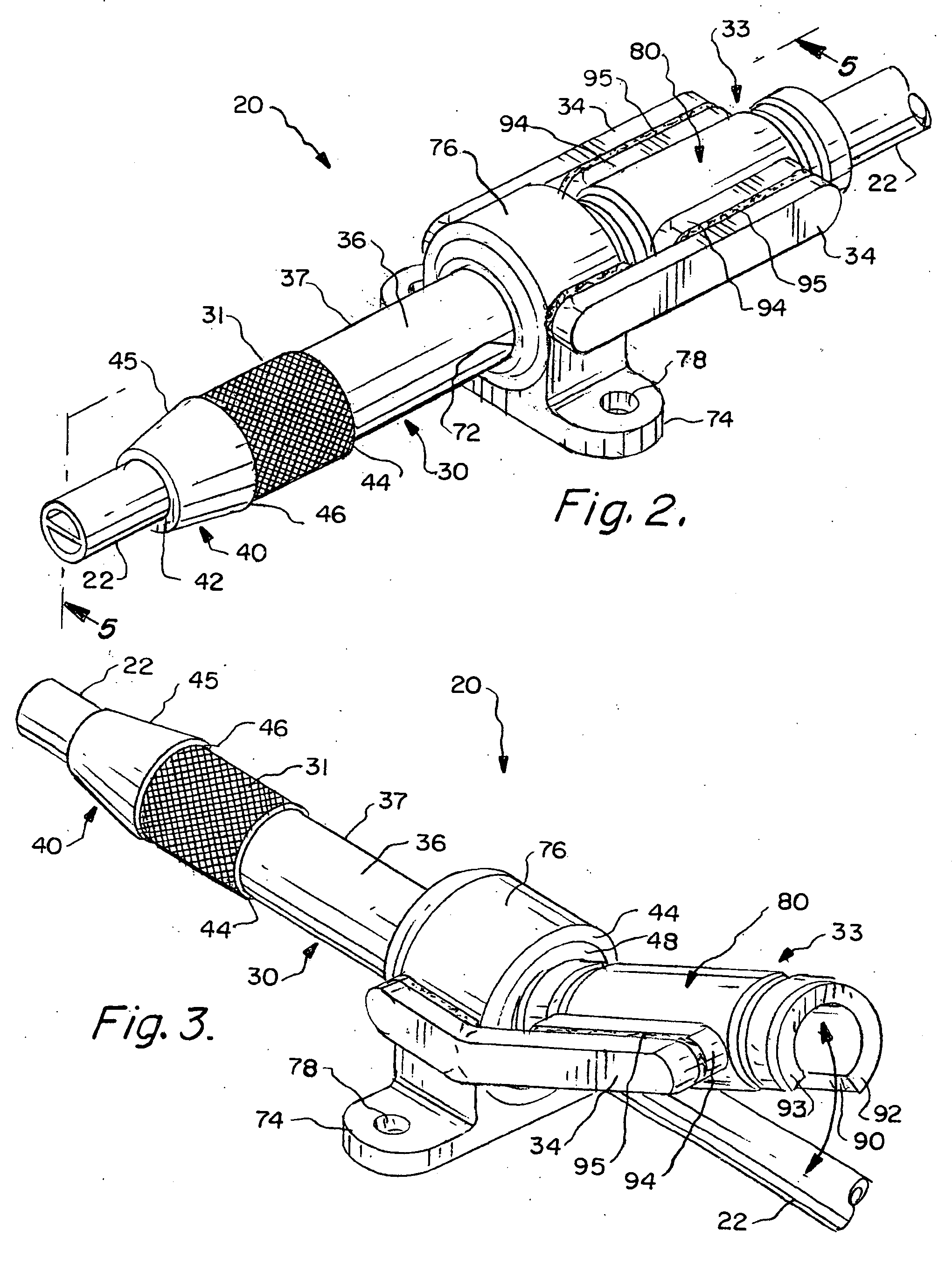
[0029]Attention is now directed to FIGS. 2-5 which depict a preferred catheter assembly 20 in accordance with the present invention. FIG. 4 best shows the...


PUM


Abstract

A medical apparatus and method of use for implanting a percutaneous catheter in a patient's body which catheter can be easily positioned, repositioned, and replaced. The apparatus includes an elongate sleeve having a tapered forward portion to facilitate its insertion through an undersized incision. The sleeve provides an interior elongate passageway which extends from a sleeve proximal end to a sleeve distal end. The sleeve is intended to be percutaneously implanted through an incision in the patient's skin so that the sleeve distal end resides subcutaneously. The sleeve outer peripheral surface carries a layer of porous material intended to be placed under the patient's outer skin layer in contact with the dermis to promote tissue ingrowth for anchoring the sleeve and forming an infection resistant barrier. The sleeve passageway is dimensioned to snugly accommodate the outer surface of catheter while permitting the catheter to slide relative to the sleeve. A sealing device is mounted around the catheter adjacent to the sleeve proximal end to prevent deleterious material from migrating into the patient's body along the catheter outer surface. A locking member secured to the sleeve can be pivoted to an unlocked portion for permitting axial and rotational movement of said catheter relative to said sleeve and or to a locked position for preventing such relative movement.

Description

RELATED APPLICATIONS[0001]This application is a Continuation-In-Part of (1) U.S. application Ser. No. 11 / 708,445 filed on Feb. 20, 2007 which claims priority based on U.S. Provisional Application 60 / 818,768 filed on Jul. 5, 2006 and (2) U.S. application Ser. No. 12 / 287,130 filed on Oct. 6, 2008 which claims priority based on U.S. Provisional Application 60 / 999,480 filed on Oct. 17, 2007. This application claims priority based on the aforementioned applications which are by reference incorporated herein.FIELD OF THE INVENTION[0002]This invention relates generally to medical technology and more particularly to a method and apparatus for implanting an elongate conduit, e.g., a catheter or cable, to extend through a patient's skin for providing long term access to an interior body site. Embodiments of the invention are useful in a variety of applications, e.g., in hemodialysis procedures to enable a catheter to provide fluid access to a patient's central venous system and / or nerve stimu...

Claims


Application Information

Patent Timeline
Patent Type & Authority Applications(United States)
IPC IPC(8): A61M25/04A61M25/16A61M25/00
CPCA61F2/0077A61M39/0247A61M2039/0294A61M2039/0273A61M2039/0261
Inventor PORTER, CHRISTOPHER H.VIDAL, CLAUDE A.REDMOND, RUSSELL J.MORAN, BYRON L.JANIS, ABRAM D.CHAPMAN, KELLY A.
Owner INCUMED LLC A NEVADA LIMITED LIABILITY
Why Eureka
Try Eureka