
Broadhead for bow hunting arrow

Inactive Publication Date: 2009-07-02
SAMES GREGORY A
View PDF6 Cites 2 Cited by
  • Summary
  • Abstract
  • Description
  • Claims
  • Application Information

AI Technical Summary

Benefits of technology

[0010]Both the triangular blades and the ring may have razor-sharp edges facing the tip end of the arrowhead. The combination of the triangular blades sloping inward towards the pointed tip end of the arrowhead for initial penetration of the target, with the annular blade following, forms a larger diameter wound to ensure a bloody trail for the hunter to track, and fixing the ring to the triangular blades provides stability and a flatter trajectory for the arrow.

Problems solved by technology

Frequently, when a large game animal, such as a deer or elk, is struck by an arrow, the animal will run away, even when mortally wounded.
The arrowhead may penetrate deeply, and the wound may close around the shaft, so that sometimes there is no significant trail of blood, or the trail of blood may be too short to aid the hunter in the task of tracking the animal.
If the wound is not mortal, the animal is often forced to endure prolonged agony.
Consequently, there is a need for a hunting arrowhead that will open a large wound to ensure a copious trail of blood, and that will be likely to inflict a fatal wound.

Method used


Image

  • Broadhead for bow hunting arrow
  • Broadhead for bow hunting arrow
  • Broadhead for bow hunting arrow

Examples


first embodiment

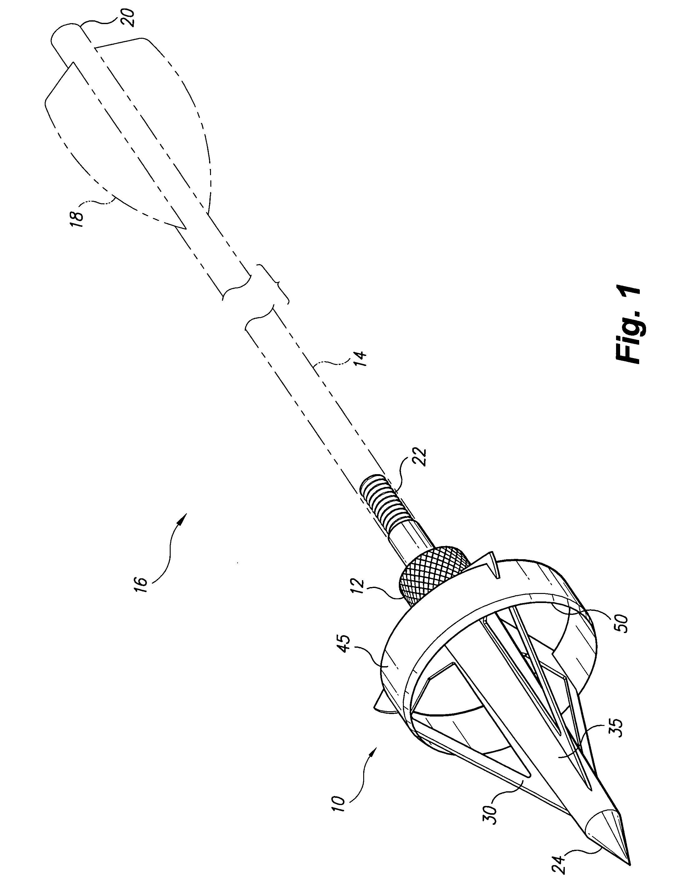
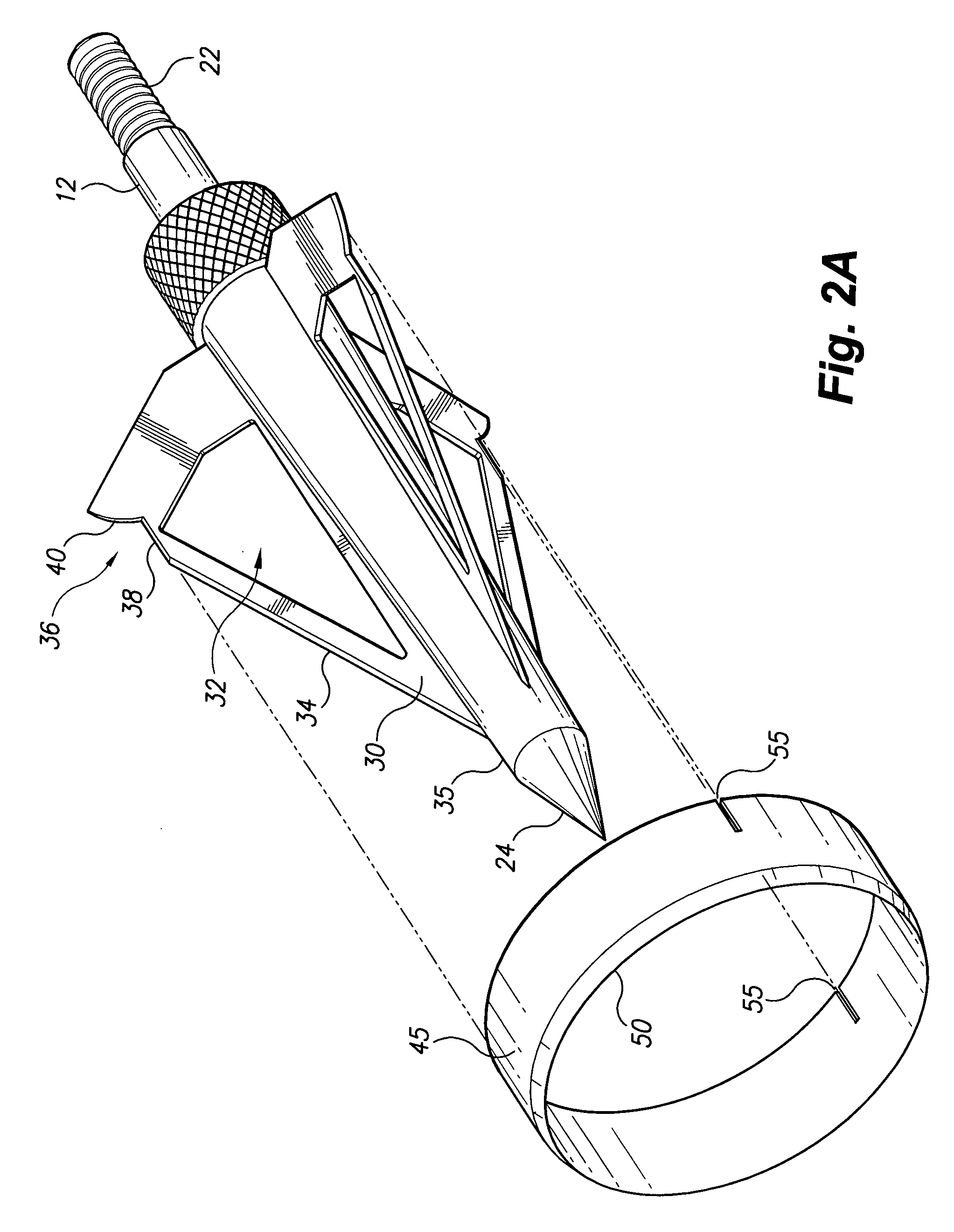
[0020]The present invention relates to a broadhead for a bow hunting arrow. FIGS. 1-3 show a broadhead according to the present invention, designated generally as 10 in the drawings. The broadhead 10 has an elongated, cylindrical ferrule 35 having a fitting 12 extending from one end adapted for attaching the broadhead 10 to the shaft 14 of an arrow 16 having conventional fletching 18 and a nock 20 for use with a bow. In the drawings, fitting 12 is shown to include a threaded stub 22 adapted for engaging a threaded socket at the end of shaft 14, the threaded stub 22 being coaxial with ferrule 35. Threaded stub 22 permits shaft 14 to be used with a field point tip arrowhead for target practice or the like, which can then be removed and replaced by broadhead 10 for hunting. However, it will be understood that fitting 12 may be any fitting adapted for attachment to the shaft of a hunting arrow, e.g., male or female press fit components, a socket that may be glued to shaft 14, etc.

[0021]...

third embodiment

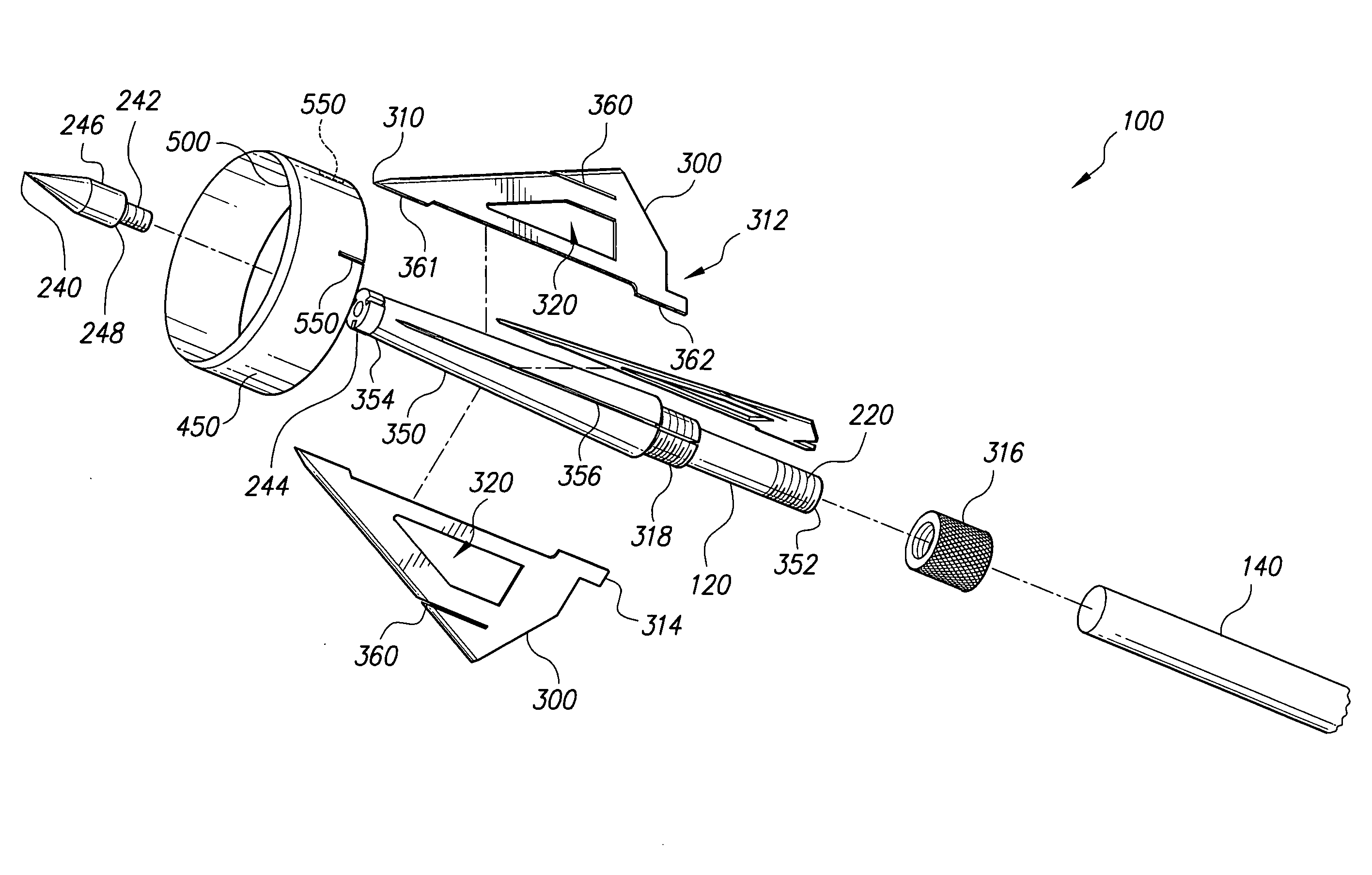
[0027]the present invention is shown in FIG. 6, with a broadhead, designated generally with the number 100. The broadhead 100 has an elongated, cylindrical ferrule 350 having a fitting 120 extending from a rear end 352 of the ferrule 350 adapted for attaching the rear end 352 of the broadhead 100 to a shaft 140 of an arrow for use with a bow, not shown. The fitting 120 is shown to include a threaded stub 220 adapted for engaging a threaded socket at the end of shaft 140, the threaded stub 220 being coaxial with the ferrule 350. Threaded stub 220 permits shaft 140 to be used with a field point tip arrowhead for target practice or the like, which can then be removed and replaced by broadhead 100 for hunting. However, it will be understood that fitting 120 may be any fitting adapted for attachment to the shaft of a hunting arrow, e.g., male or female press fit components, a socket that may be glued to shaft 140, etc.

[0028]A detachable pointed tip 240 is attached at a forward end 354 of...


PUM


Abstract

The broadhead for bow hunting arrow is an arrowhead having: a ferrule; a plurality of planar, generally triangular blades extending radially from the ferrule; a fitting for attaching the arrowhead to an arrow shaft; a pointed tip; and a ring or annular blade mounted to the outermost edges of the triangular blades. In one embodiment, the triangular blades have notches defined therein, and the ring has slits corresponding to the triangular blades extending into the body of the ring that the upper legs of the notches engage to prevent rotation of the ring. In another embodiment, the triangular blades have slots and the ring has slits extending into the ring with the slots engaging the slits to prevent rotation of the ring. Alternatively, the ring may be fixed to the triangular blades by welding or by any other means. The broadhead is particularly well suited for hunting large game animals.

Description

CROSS-REFERENCE TO RELATED APPLICATION[0001]This application claims the benefit of U.S. Provisional Patent Application Ser. No. 61 / 006,178, filed Dec. 28, 2007.BACKGROUND OF THE INVENTION[0002]1. Field of the Invention[0003]The present invention relates to arrowheads for archery, and more particularly to a broadhead for a bow hunting arrow having a cutting ring that promotes bleeding.[0004]2. Description of the Related Art[0005]Archery is the common art of using a bow to shoot arrows. Historically, a bow and arrow combination was used for warfare and hunting, until the advance of firearms. Today, archery has evolved into a precision sport that is commonly engaged in by hunters of wild game.[0006]Frequently, when a large game animal, such as a deer or elk, is struck by an arrow, the animal will run away, even when mortally wounded. The hunter must often track his game. The arrowhead may penetrate deeply, and the wound may close around the shaft, so that sometimes there is no signific...

Claims


Application Information

Patent Timeline
IPC IPC(8): F42B6/04
CPCF42B6/08
Inventor SAMES, GREGORY A.
Owner SAMES GREGORY A
Learn More