
Spout for forming and saving water

Active Publication Date: 2009-07-02
NEOPERL
View PDF7 Cites 20 Cited by
  • Summary
  • Abstract
  • Description
  • Claims
  • Application Information

AI Technical Summary

Benefits of technology

[0017]The spout is mounted on an outlet of a faucet to allow water to flow through the sieve assembly, the inlet valve and the distributor and mix with air to become foam. Then the foaming water flows through th

Problems solved by technology

Once jammed, the foaming nets (73) block flow of water and may cause the water to back up and flow out of the elongated holes (710) or, if water pressure is too high, causes rupture or breakage of the spout that must therefore be replaced.
Furthermore, the conventional spout cannot regulate water flow.

Method used


Image

  • Spout for forming and saving water
  • Spout for forming and saving water
  • Spout for forming and saving water

Examples


Embodiment Construction

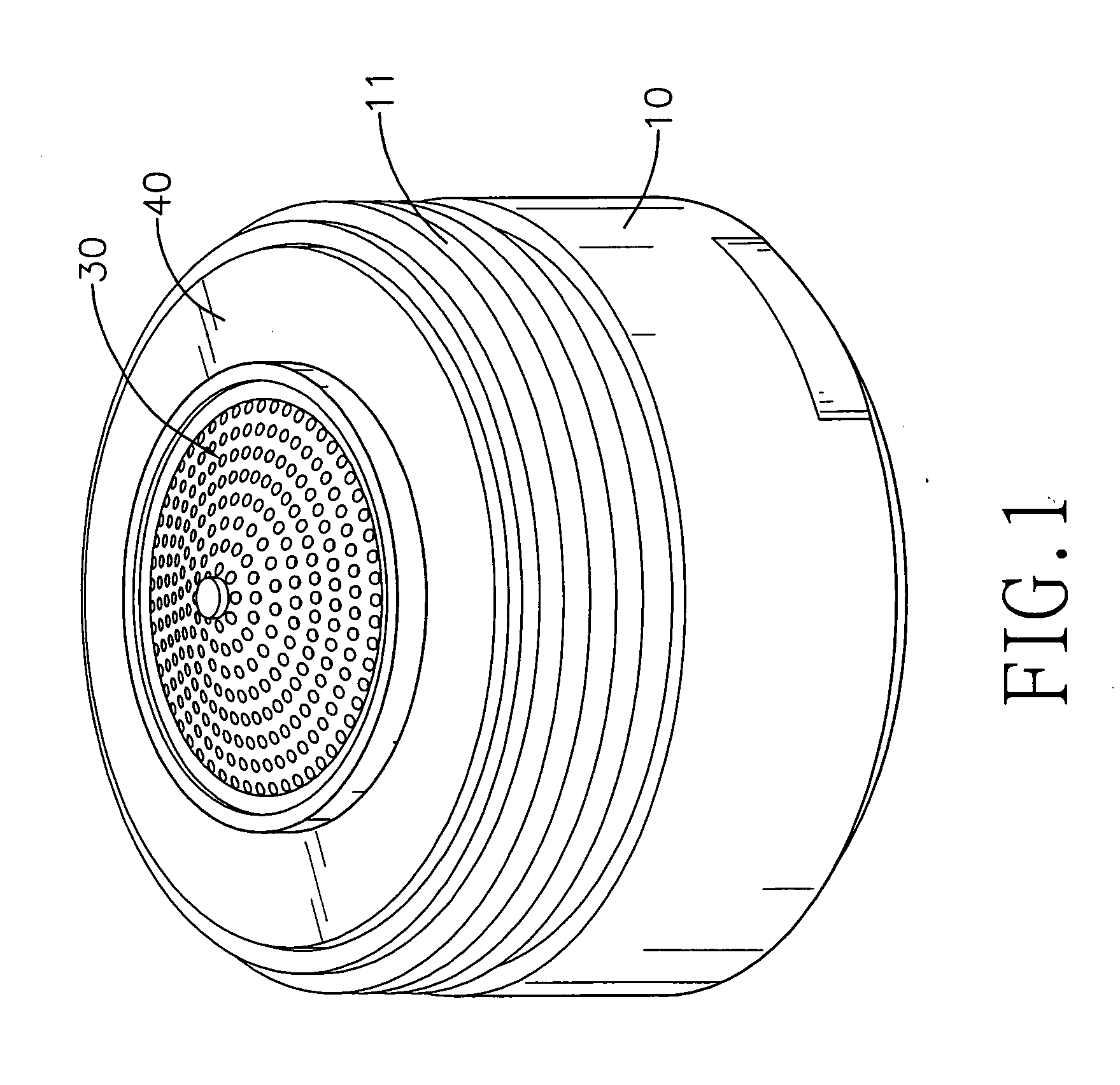
[0025]With reference to FIGS. 1 and 2, a spout for foaming and saving water in accordance with the present invention is mounted on an outlet of a faucet, foams and saves water flowing out of the faucet and comprises a shell (10), a foaming assembly (20), a sieve assembly (30), a washer (40) and a regulator (50).

[0026]With further reference to FIG. 3, the shell (10) is attached to the outlet of the faucet and has an outer surface, a faucet end, an inner surface and an outlet end, a thread (11) and a stopper (12). The thread (11) is fastened to the outlet of the faucet and is formed around the outer surface of the shell (10) near the faucet end. The stopper (12) is formed around the inner surface of the shell (12) near the outlet end.

[0027]The foaming assembly (20) is mounted in the shell (10), abuts the stopper (12) of the shell (10) and has a sleeve (21), a distributor (23), a foaming ring (24) and an inlet valve (22).

[0028]The sleeve (21) is mounted in the shell (10) and has a bott...


PUM


Abstract

A spout for foaming and saving water has a shell, a foaming assembly mounted in the shell, a sieve assembly mounted on a faucet end of the foaming assembly and a regulator mounted through the foaming assembly. The foaming assembly has a sleeve, a distributor mounted in the sleeve, a foaming ring mounted between the sleeve and the distributor and an inlet valve mounted on a faucet end of the sleeve. The spout is mounted on an outlet of a faucet to allow water to flow through the sieve assembly and the foaming assembly and mix with air to foam to provide foaming water flowing out of the spout. Impurities in the water do not clog the foam assembly and water flow is regulated with the regulator selectively mounted in a water flow hole of the inlet valve.

Description

BACKGROUND OF THE INVENTION[0001]1. Field of the Invention[0002]The present invention relates to a spout, especially to a spout for a faucet causing foaming to save water.[0003]2. Description of the Prior Arts[0004]With reference to FIG. 5, a conventional spout is mounted on an outlet of a faucet, foams and saves water flowing out of the faucet and comprises a shell (60), a foaming assembly (70) and a sieve (80).[0005]The shell (60) is tubular and has a faucet end, an outer surface, an inner surface and a thread. The thread is formed around the outer surface of the shell (60) near the faucet end and may be fastened onto the outlet of the faucet.[0006]The foaming assembly (70) has a sleeve (71), a water flowing net (72), multiple foaming nets (73) and a distributor (74).[0007]The sleeve (71) is tubular, is metal, is securely mounted in the shell (60) and has a sidewall, an abutting rim (711) and multiple elongated holes (710). The sidewall has a faucet end and an outlet end. The abut...

Claims


Application Information

Patent Timeline
IPC IPC(8): E03C1/084
CPCE03C1/084Y02A20/411
Inventor KAO, YU-YUEH
Owner NEOPERL
Learn More