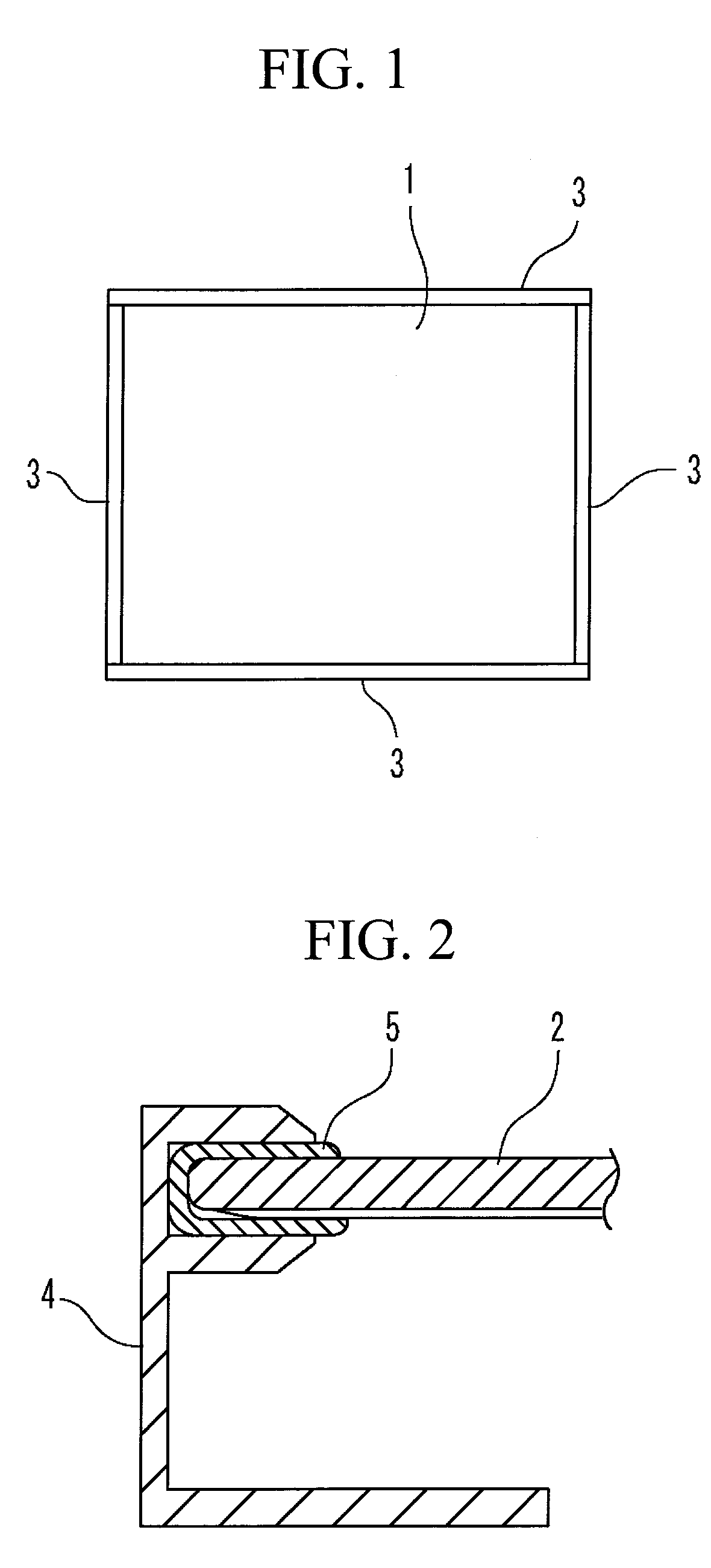
Solar panel

a solar panel and solar panel technology, applied in the field of solar panels, can solve the problems of affecting the operation of solar cells, affecting the safety of solar cells, and the difference in thermal expansion between glass and aluminum, and achieve the effect of simple structure and easy manufacturing

Inactive Publication Date: 2009-07-02
MITSUBISHI HEAVY IND LTD
View PDF3 Cites 64 Cited by
  • Summary
  • Abstract
  • Description
  • Claims
  • Application Information

AI Technical Summary

Benefits of technology

[0021]An object of the present invention is to provide a solar panel which has simple structure and which is easy to manufacture and also to provide a manufacturing method thereof.

Problems solved by technology

Of these conditions, moisture entry into the solar cell module is the most serious problem which has an influence on the life.
However, there is a difference in thermal expansion between glass and aluminum; thus, firmly fixing the both leads to a possibility of detachment of the bonded part or glass crack, which is not preferable.
Moreover, an uneven amount of adhesive application possibly results in direct contact between the glass and the aluminum, in this case a temperature difference arises between the glass and the aluminum depending on a meteorological condition, thus resulting in a possibility of “thermal crack” in which glass cracks, which is not preferable.
However, when the gasket is used in such a manner, bonding is not provided between the glass and the gasket and also between the gasket and the aluminum frame, and thus there is a gap or a space therebetween.
Long-term moisture accumulation results in a possibility of inducing moisture entry into the solar cell module.
In a case where the solar cell module body is displaced and one part of the light receiving surface of the solar cell module body is hidden by the frame structure, a desired output may not be obtained.

Method used


Image

  • Solar panel
  • Solar panel
  • Solar panel

Examples


first embodiment

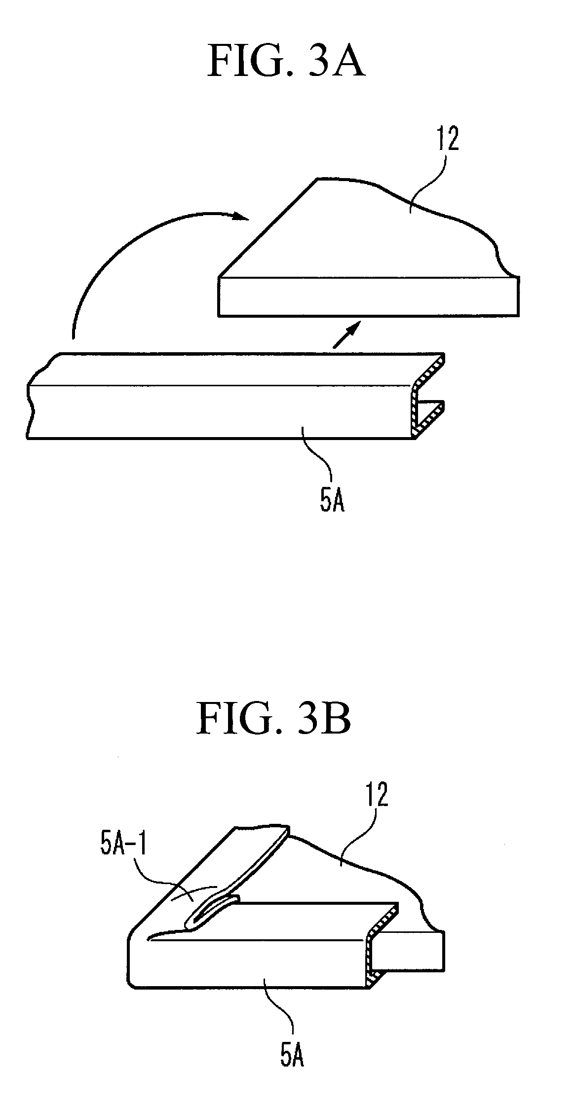
[0069]FIGS. 3A and 3B are perspective views each showing one example in which a substantially U-shaped gasket 5A is fitted at the periphery of a rectangular plate-like solar cell module body 12. Surrounding the entire periphery of the solar cell module body 12 with one gasket 5A as shown in FIG. 3A results in formation of a portion 5A-1 folded at a corner part as shown in FIG. 3B, making it difficult to assemble it into a frame structure. FIGS. 4A and 4B are perspective views each showing one example in which substantially U-shaped gaskets 5B are fitted to the periphery of the rectangular plate-like solar cell module body 12. If the four gaskets 5B are separately fitted to four sides of the solar cell module body 12 as shown in FIG. 4A, the gaskets make contact with each other only at a point 5B-1 of a corner part as shown in FIG. 4B, which is not sufficient to prevent water entry into the solar cell module body.

[0070]FIGS. 5A and 5B are perspective views each showing one example in...

second embodiment

[0074]Next, a solar panel according to a second embodiment of the present invention will be described. FIGS. 7A and 7B are sectional views showing conditions before and after a gasket 5C and the solar cell module body 12 are fitted with each other. FIG. 7A shows the condition before the fitting and FIG. 7B shows the condition after the fitting. As shown in FIG. 7A, the cross section of the gasket 5C is substantially U-shaped. As shown in FIG. 7B, when the solar cell module body 12 is fitted with the gasket 5C, the leading end of the gasket 5C turns up, so that water entry into the solar cell module body 12 may be permitted.

[0075]FIGS. 8A and 8B are sectional views showing conditions before and after a gasket and the solar cell module body are fitted with each other in the second embodiment of the present invention. In the present invention, as shown in FIG. 8A, a projection part 6-4 is formed at the end part of each of an upper side part 6-1 and lower side part 6-2 of the gasket 6C ...

third embodiment

[0076]Next, a solar panel according to a third embodiment of the present invention will be described. FIGS. 9A and 9B are sectional views showing conditions in which the gasket and the solar cell module body are fitted with each other. As shown in FIG. 9A, a space, although small, may be formed between the gasket 5D and the solar cell module body 12. In this space, moisture 10 possibly enters, although in a small amount, due to a capillarity phenomenon, dew condensation, or the like. Therefore, in the present invention, as shown in FIG. 9B, holes 6-5 are provided in a gasket 6D so that the moisture can be discharged as shown by arrows in the figure. In this case, the moisture entering the inside is small in amount and held in the small gap between the gasket 6D and the solar cell module body 12 due to surface tension or a capillarity phenomenon. Therefore, such moisture discharge is achieved mainly by vaporization. Thus, it is preferable that the holes 6-5 of the gasket 6D is large ...


PUM

PropertyMeasurementUnit
sizeaaaaaaaaaa
angleaaaaaaaaaa
vertex angleaaaaaaaaaa

Abstract

A solar panel according to the present invention includes a solar cell module body (12), a gasket part (6A to 6F), and a frame structure (13). The gasket part includes a substantially U-shaped structure, having an upper side part, a lower side part, and a connecting part connecting an end of the upper side part and an end of the lower side part, in which the upper side part and the lower side part on the open side abut the peripheral edge part of the solar cell module body and sandwiches the solar cell module body by an elastic force. The frame structure (13) has a female fitting part (13-1), and fitting of the gasket part with the female fitting part supports the solar cell module body via the gasket part. The female fitting part has a drain hole (13-3) which can drain the water in the female fitting part.

Description

TECHNICAL FIELD[0001]The present invention relates to a solar panel and a manufacturing method thereof.BACKGROUND ART[0002]Great attention has been given to clean energy such as photovoltaic power generation in view of environmental problems.[0003]A solar panel is an electric generator used outdoors, and is required to have sufficient durability under very severe conditions, such as ultraviolet rays, wind and snow, salt damage, acid rain, freezing, dirt accumulation, microorganism generation. Of these conditions, moisture entry into the solar cell module is the most serious problem which has an influence on the life. Thus, in many solar panels, glass is used for a substrate or a windshield with the periphery thereof bonded to a frame structure of aluminum or the like. Then, the solar panel is installed in the platform by way of a frame structure.[0004]Japanese Laid Open Patent Application JP-P2003-78154A discloses a mounting structure of such a solar cell module. FIG. 1 is a plan vi...

Claims


Application Information

Patent Timeline
Patent Type & Authority Applications(United States)
IPC IPC(8): H01L31/048H01S4/00H02S20/00
CPCF24J2/4612F24J2/4614F24J2/465Y10T29/49002F24J2/5211Y02E10/47H02S20/00Y02E10/50F24S25/20F24S40/40F24S40/44F24S80/70F24S2025/016H02S30/10
Inventor HORIOKA, TATSUJIISHIDA, NOBUHISAURAKATA, HISATAKAMAMASE, SINICHIRO
Owner MITSUBISHI HEAVY IND LTD
Why Eureka
Try Eureka