Mop with attached wringer

a technology of wringer and wringer cup, which is applied in the field of wringer with attached wringer, can solve the problems that wringing is not always completely effective, and achieve the effects of preventing re-absorption, enhancing water draining, and allowing water to drain out of the wringer cup more quickly and effectively

Inactive Publication Date: 2009-07-02
LIBMAN
View PDF22 Cites 6 Cited by
  • Summary
  • Abstract
  • Description
  • Claims
  • Application Information

AI Technical Summary

Benefits of technology

[0004]The applicant has developed an innovative wringer cup and connector assembly for the mop fibers. In an embodiment the wringer cup has holes in it that may permit water to drain out of the wringer cup more quickly and effectively so as to help prevent re-absorption. In an embodiment the wringer cup includes inwardly directed ribs and the ribs include perforations to enhance the draining of water from the mop fibers. In an embodiment the connector assembly may be configured to allow for easier assembly of the mop fibers to a mop handle.

Problems solved by technology

The wringing is not always completely effective, however.

Method used


Image

  • Mop with attached wringer
  • Mop with attached wringer
  • Mop with attached wringer

Examples


Embodiment Construction

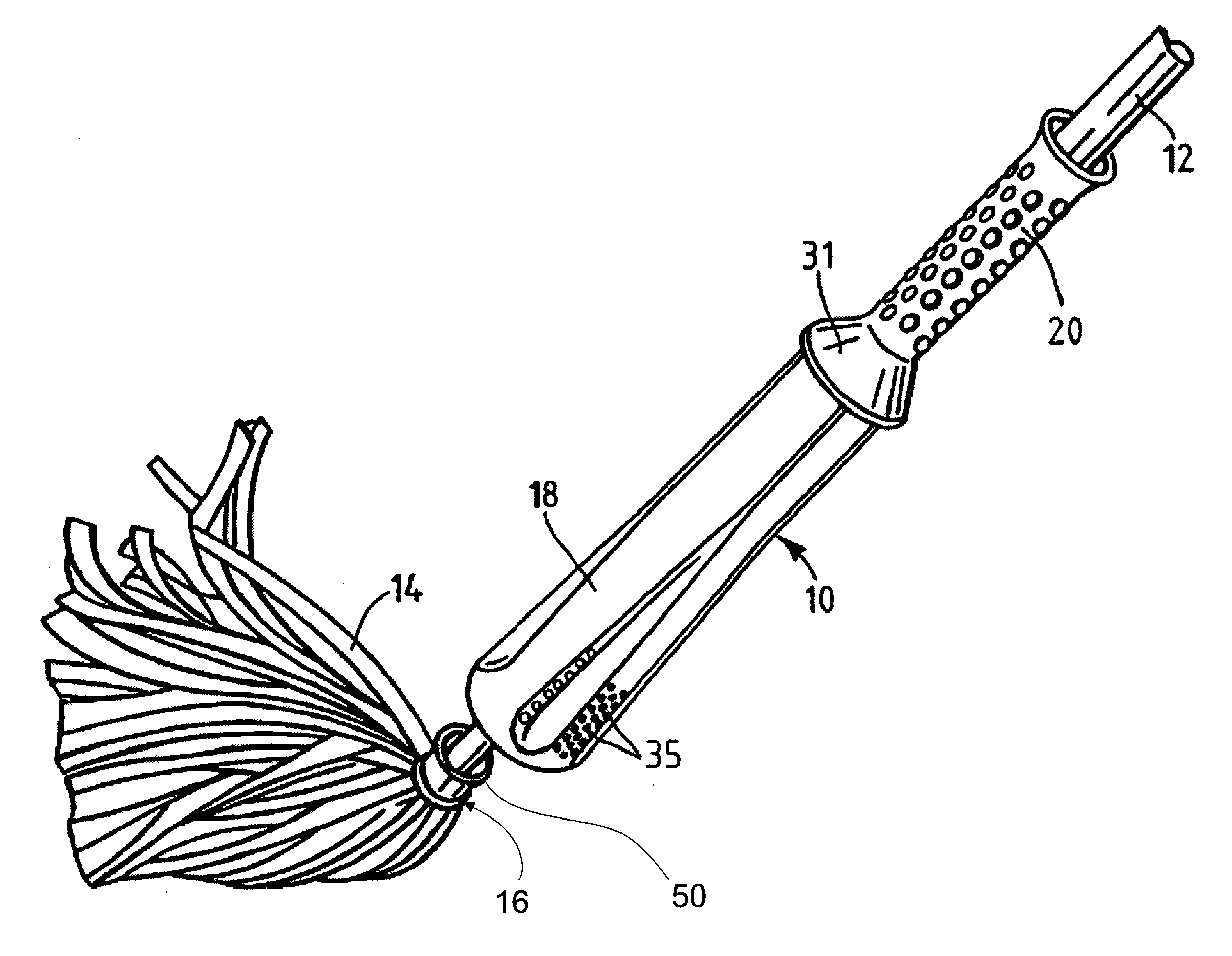
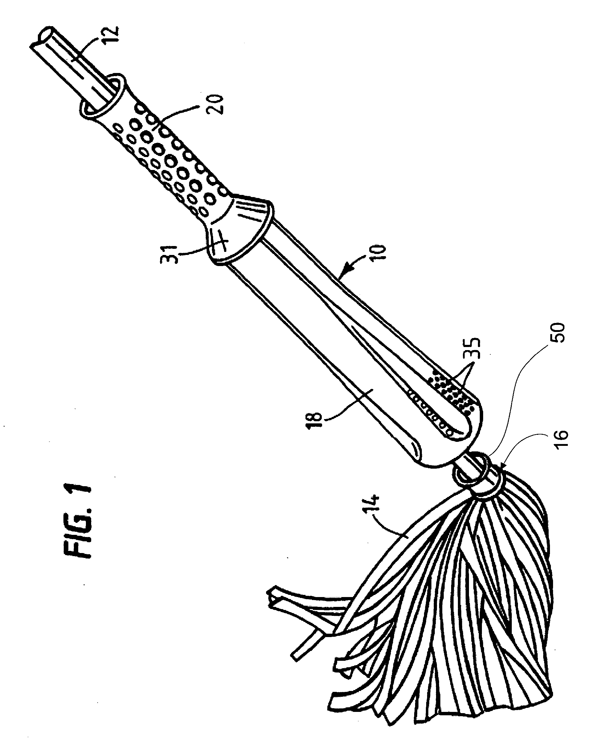
[0019]FIGS. 1-4 show one embodiment of a mop 10 in accordance with the present invention. Like conventional wringer mops, the illustrated mop includes a handle 12, a set of mop elements 14 on an end 16 of the handle 12, and a wringer cup 18. To fasten the mop elements 14 to the end 16 of handle 12, a connector assembly 50 is provided.

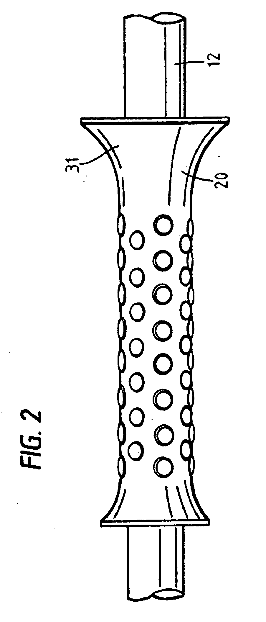
[0020]It is conventionally known that the handle for such mops can be a lightweight metal tube. The illustrated handle includes an optional hand grip 20, discussed below.

[0021]The mop elements 14 that are illustrated take the form of flat strips. It is conventionally known that such strips can be made from (for example) water-absorbing non-woven fibrous material that is around 18 or 19 inches long and about 0.15 inch thick in its non-compressed state. Other materials could also be used.

[0022]As seen in FIGS. 3 and 4, the illustrated wringer cup 18 is disposed on the handle 12 above the mop elements 14, and has an outer wall 23 that tapers outwardly towa...


PUM


Abstract

A connection assembly configured to secure a mop head to an elongate member is provided. In one embodiment, a connector may include an insert having a plurality of tabs with an inner portion and an outward extending outer portion that extends radially outward from and traverse to an elongate member when the insert is properly mounted to the elongate member. The connector may include an inner member comprising a plurality of depressions configured to engage the inner portion of the plurality of tabs of the insert. A collar having an inner wall may also be utilized, wherein at least a portion of the inner wall is of a generally circular cross-section configured to engage the outward extending outer portion of the plurality of tabs. Connection assemblies may further comprise a wringer cup configured to be mounted on the elongate member.

Description

[0001]This application is a continuation of U.S. patent application Ser. No. 11 / 189,127, filed Jul. 25, 2005, which is a continuation-in-part of application Ser. No. 10 / 356,896, filed on Feb. 3, 2003, now U.S. Pat. No. 6,920,664, which is a continuation-in-part of U.S. application Ser. No. 29 / 145,583, filed on Jul. 25, 2001, now U.S. Pat. No. D474,869. The present invention relates generally to mops, and more particularly to mops with attached wringer cups.BACKGROUND OF THE INVENTION[0002]One type of mop that has found commercial success is in the marketplace is a mop having an attached wringer cup, like the one disclosed in U.S. Pat. No. 5,060,338. Other examples may be found in U.S. Pat. Nos. 1,709,622; 3,364,512; 3,946,457; and 4,809,287; and German published patent Application No. DE 3607121 A1.[0003]The wringer cups used on these kinds of mops often have grooves or ribs on the inside. When the cone-shaped wringer cup is pushed down over the mop fibers, the ribs help to squeeze ...

Claims


Application Information

Patent Timeline
Patent Type & Authority Applications(United States)
IPC IPC(8): A47L13/00A47L13/14
CPCA47L13/14
Inventor LIBMAN, ROBERT J.BERTI, ENZOBIZZOTTO, MARCOPELLACINI, ROBERTO
Owner LIBMAN
Why Eureka
Try Eureka