
Electrical splice connector

a technology of splicing connectors and connectors, applied in the direction of connection end caps, coupling device connections, contact members penetrating/cutting insulation/cable strands, etc., can solve the problems of heating or cooling of cables at the junction

Inactive Publication Date: 2009-06-25
3M INNOVATIVE PROPERTIES CO
View PDF25 Cites 19 Cited by
  • Summary
  • Abstract
  • Description
  • Claims
  • Application Information

AI Technical Summary

Problems solved by technology

Connecting incoming cables with one or more outgoing cables can potentially result in heating the cables at the junction, or heating the electrical connector employed to form the junction.

Method used


Image

  • Electrical splice connector
  • Electrical splice connector
  • Electrical splice connector

Examples


Embodiment Construction

[0024]In the following Detailed Description, reference is made to the accompanying drawings, which form a part hereof, and in which is shown by way of illustration specific embodiments in which the invention may be practiced. In this regard, directional terminology, such as “top,”“bottom,”“front,”“back,”“leading,”“trailing,” etc., is used with reference to the orientation of the Figure(s) being described. Because components of embodiments can be positioned in a number of different orientations, the directional terminology is used for purposes of illustration and is in no way limiting. It is to be understood that other embodiments may be utilized and structural or logical changes may be made without departing from the scope of the present invention. The following detailed description, therefore, is not to be taken in a limiting sense, and the scope of the present invention is defined by the appended claims.

[0025]It is to be understood that the features of the various exemplary embodi...


PUM


Abstract

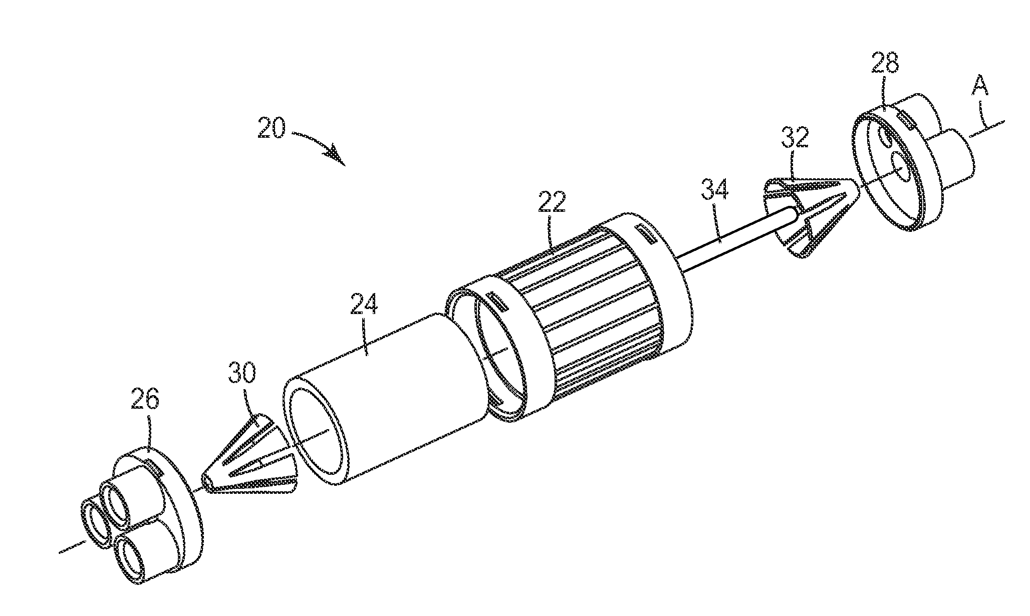
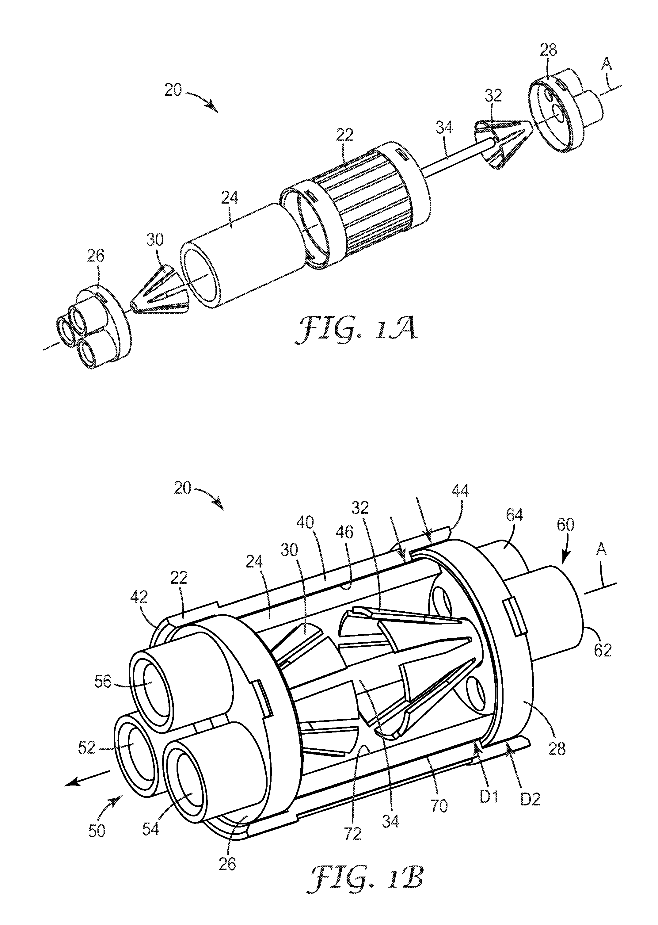
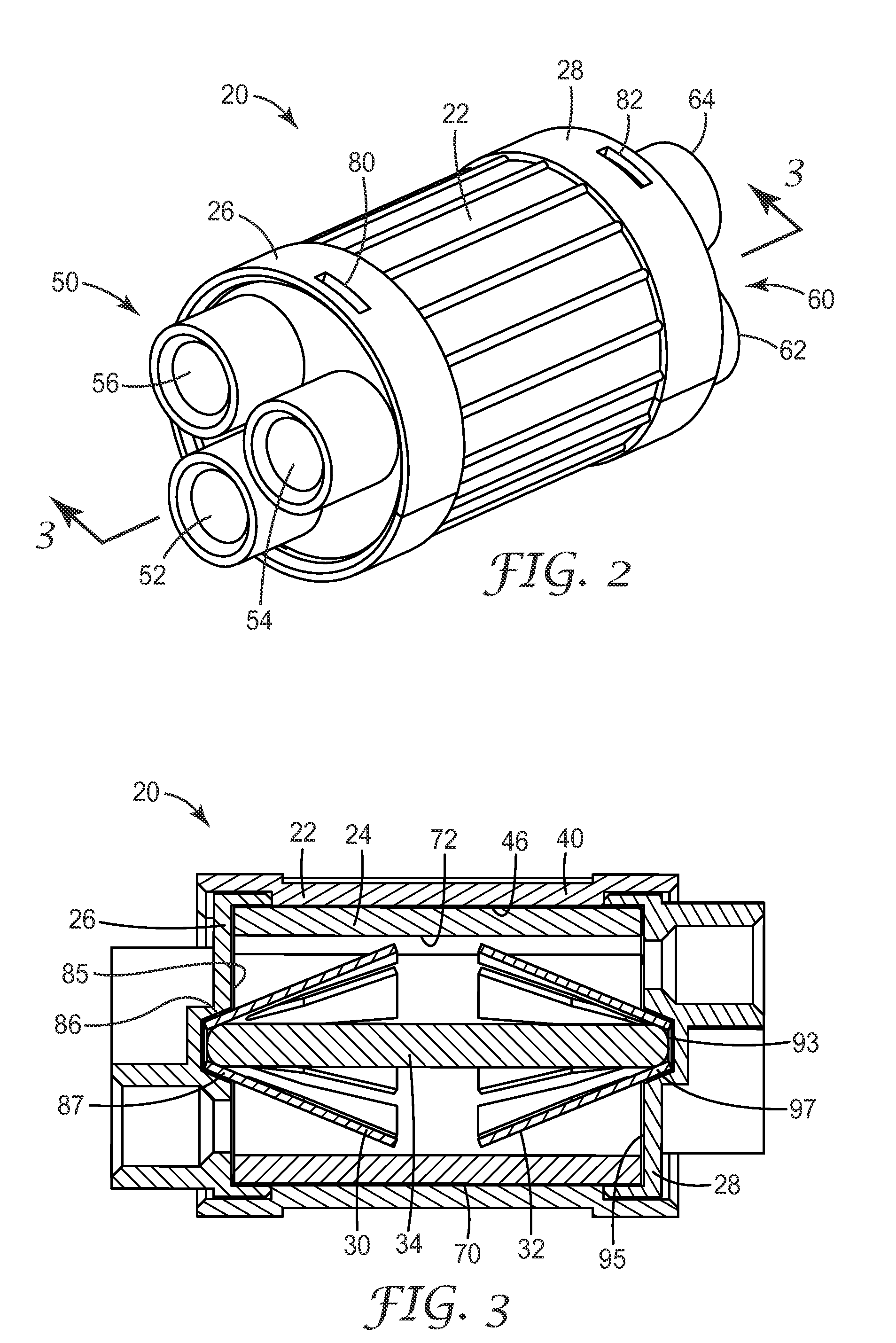
An electrical splice connector includes a housing, a conductive member retained within the housing and defining a longitudinal axis, and at least two biasing members circumferentially disposed about the longitudinal axis of the conductive member and biased toward the conductive member. Each of the biasing members is configured to urge conductors inserted into the housing into electrical contact with the conductive member.

Description

BACKGROUND[0001]Electric cables are broadly employed in a variety of industries and applications, including applications in communications, telecommunications, automotive, and / or appliances. Some electrical cables distribute power across vast power grids or networks, moving electricity from power generation plants to the consumers of electrical power, and moving electricity from one power grid to another power grid. Other electrical cables are employed in wiring homes and / or businesses.[0002]Electrical cables generally include a conductive core (typically copper or aluminum) and may include one or more layers of surrounding insulating material. Some power cables include multiple twisted conductive wires. Electrical cables are constructed to carry high voltages (greater than about 50,000 volts), medium voltages (between about 1,000 volts and about 50,000 volts), or low voltages (less than about a 1,000 volts).[0003]It is sometimes desirable to periodically form a splice or a junction...

Claims


Application Information

Patent Timeline
IPC IPC(8): H01R11/09
CPCH01R4/22H01R13/5216H01R11/09H01R4/4818H01R4/485H01R4/4821H01R4/4842H01R4/48185
Inventor JANULIS, EUGENE P.MAHONEY, DAVID V.SJOLANDER, GARRY L.TWIGG, RICHARD D.
Owner 3M INNOVATIVE PROPERTIES CO
Learn More