
Image processing apparatus, image processing method and computer program

a technology of image processing and image processing device, which is applied in the direction of digital output to print units, instruments, digitally marking record carriers, etc., can solve the problems of deteriorating the quality of images read, besides the cost of increasing the accuracy of the reading device, and unable to eliminate the showthrough of document background having a lot of showthrough

Inactive Publication Date: 2009-06-25
CANON KK
View PDF3 Cites 27 Cited by
  • Summary
  • Abstract
  • Description
  • Claims
  • Application Information

AI Technical Summary

Benefits of technology

The present invention is an image processing apparatus that can remove background of an image on a document. It includes a front reading unit for reading image information on the front side of the document, a rear reading unit for reading image information on the rear side of the document, and a computing unit for calculating a first background level from the image information on the front side and adjusting it based on the density of the image information on the rear side. The apparatus can then remove the background of the image on the front side using the adjusted background level. This invention helps to improve the quality of the image by removing showthrough, which is the appearance of the rear side image in the front side image.

Problems solved by technology

This constitutes a primary factor of deteriorating the quality of the images read.
In this case, although a contrivance to prevent deterioration in the document color reproducibility is made using formulae, since it does not consider the unexpected appearance of the rear side image, it cannot eliminate the showthrough from the document background having a lot of showthrough.
Furthermore, it requires the size of a subtracting combining circuit whose input is two sheets of images, the processing cost and a memory, and these factors present another problem besides the cost for increasing the accuracy of the reading device.

Method used


Image

  • Image processing apparatus, image processing method and computer program
  • Image processing apparatus, image processing method and computer program
  • Image processing apparatus, image processing method and computer program

Examples


embodiment 1

[0024]As a means for electronically reading information on a document on which the information is written, an image reader such as a copying machine, a fax machine and a scanner for computer input is used.

[0025]In addition, as an automatic double-side reader that automatically reads image information on the document, a front side image and a rear side image, without the intervention of the user, a method of reading the document by reversing the two sides thereof through an inverting section is installed and put to practical use most widely.

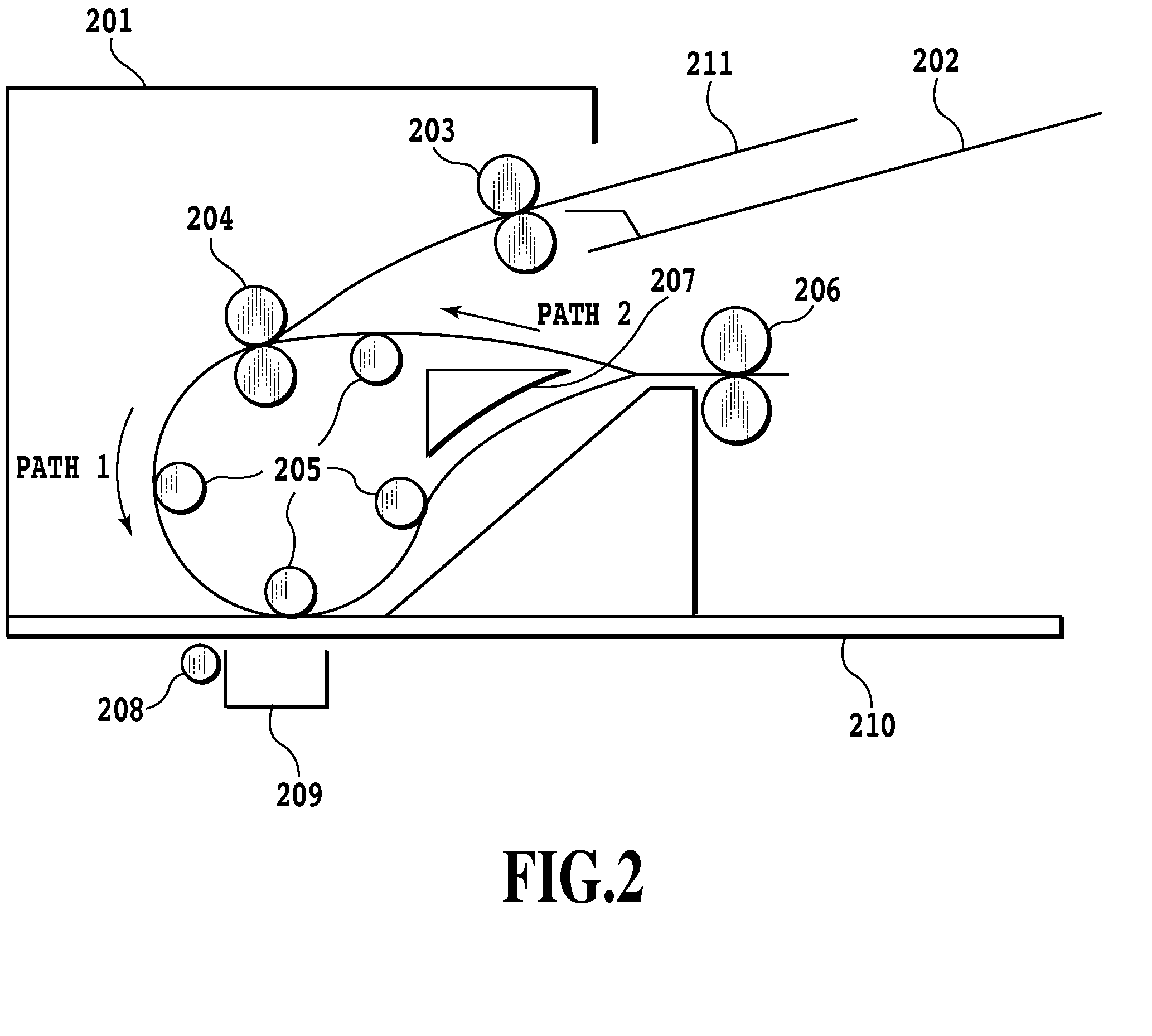
[0026]The automatic double-side reader employing such a document inverting section is denoted by the reference numeral 201 in FIG. 2.

[0027]In the present specification, unless otherwise specified, the description is made under the assumption that a color document is read in the form of color image data.

[0028]FIG. 2 shows a document tray 202, pickup rollers 203, conveyor rollers 204, rollers 205, rear side conveyor / paper output rollers 206, a separ...

embodiment 2

[0063]In the foregoing first embodiment, the showthrough correction values g(x, y) in the nonlinear background removal formulae are dynamically varied for respective pixels. Thus, the formulae vary for respective pixels by considering the rear side image because the values RW, GW, and BW are constant. More specifically, as for the divisor in Expression 1 shown in FIG. 9, when the background level is uniform within the image, it can be calculated in advance because the coefficients become constant. In contrast with this, when the components of the g(x, y) are made offset, recalculation becomes necessary for respective pixels.

[0064]In view of this, concerning the coefficients that require recalculation, a plurality of their candidates can be prepared in advance so that they are switched in accordance with the offset of the background level of the rear side image.

[0065]For example, eight sets of (Rcoef(n), Gcoef(n), Bcoef(n)), where n=0−7, are prepared as the candidates of the coeffici...

embodiment 3

[0068]Although the first and second embodiments are described in the assumption that the degree of transparency of the rear side image is uniform regardless of the type of paper, the degree of transparency of the rear side image to the front side image can be taken into account by providing the reading apparatus with a sensor that can measure the thickness of the paper.

[0069]The sensor can be one that senses the thickness of the paper. Alternatively, the sensor can be one that senses the transparency of the paper.

[0070]More specifically, in the step of creating the offset of the background level at step S107 of FIG. 1, a decision is made when the paper is thin that the rear side image has a large effect on the front side image. Then, the amount of adjustment of the background level and the fluctuations thereof are increased. In contrast, when the paper is thick, the amount of the adjustment and the fluctuations thereof are reduced.

[0071]This makes it possible to realize the showthro...


PUM


Abstract

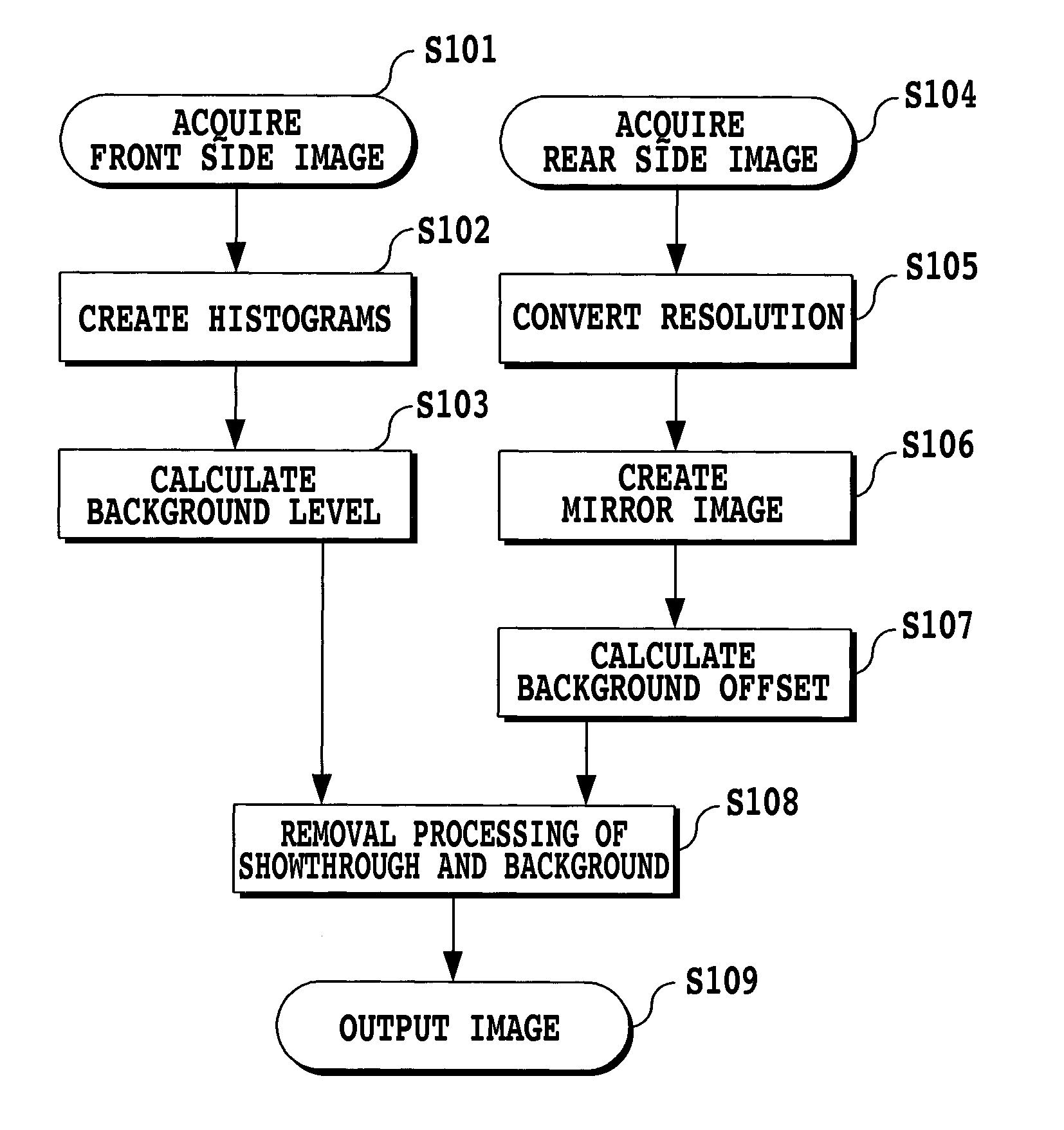
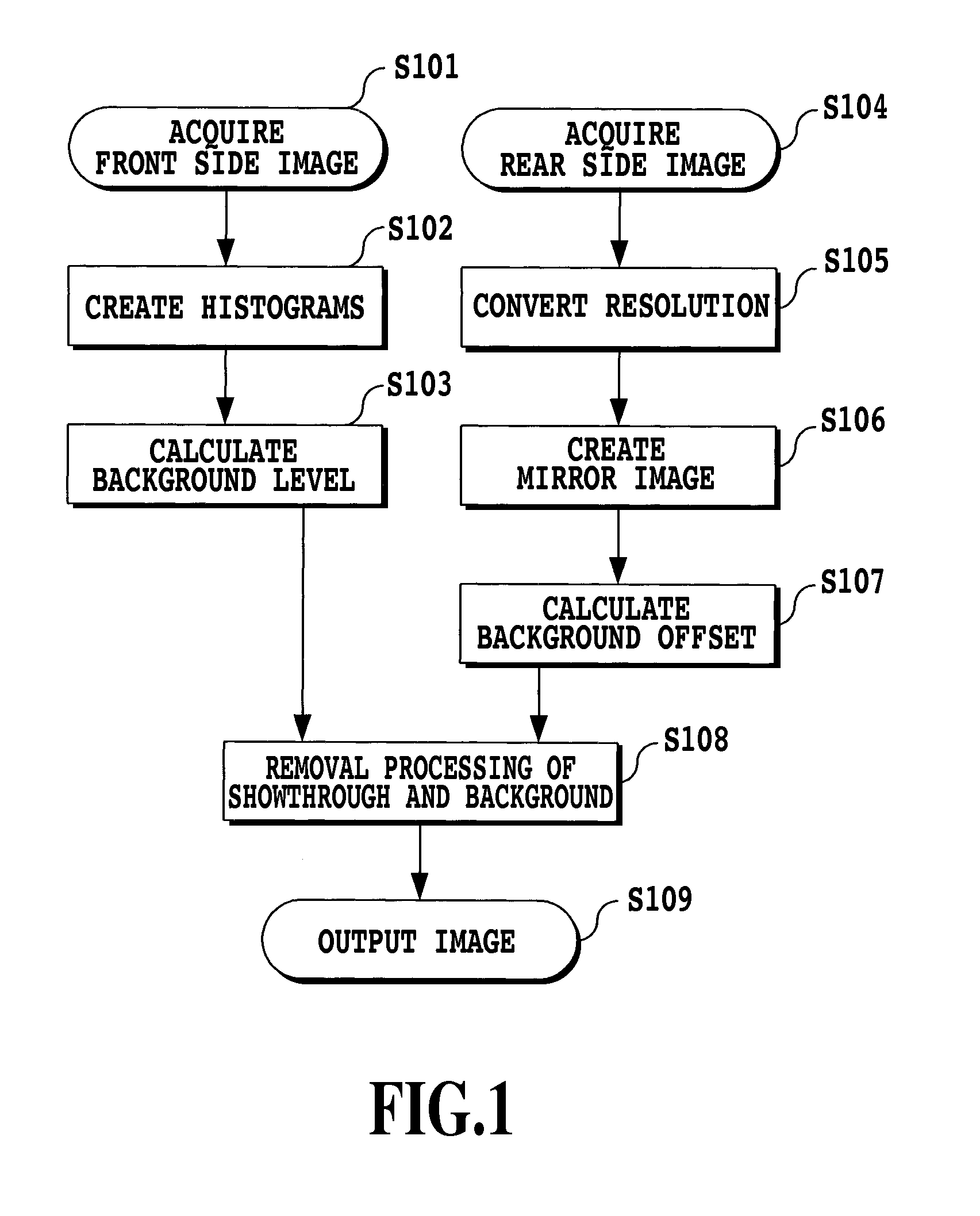
A problem of the present invention is to prevent showthrough of a rear side image to a front side image without using any complicated processing at a time of reading out both sides of a document. To solve the problem, an image processing apparatus in accordance with the present invention reads out image information on the front side and rear side of a document; calculates a first background level from the image information on the front side; calculates a second background level by adjusting the first background level according to the first background level calculated and the density of the image information on the rear side; and removes the background of the front side using the second background level.

Description

BACKGROUND OF THE INVENTION[0001]1. Field of the Invention[0002]The present invention relates to an image processing apparatus, image processing method and computer program, which read images on both sides of a document and prevent showthrough in which the printing on the rear side is visible through the paper.[0003]2. Description of the Related Art[0004]Conventionally, an image reader, typified by a scanner, fax machine, and copying machine can automatically acquire an front side image and a rear side image of a document using an ADF (Auto Document Feeder) and the like at the time when reading out the images from a document. Thus, a user need not place the document printed on both sides on a document glass twice, the front side and the rear side each, so that the load of acquiring the document printed on both sides is reduced. In addition, recently, it has become possible to acquire the front side image and rear side image of a document simultaneously through a seeming single readi...

Claims


Application Information

Patent Timeline
Patent Type & Authority Applications(United States)
IPC IPC(8): G06F3/12
CPCH04N1/4095H04N1/024H04N1/00
Inventor TAMURA, HIROKAZU
Owner CANON KK
Learn More