
System and a method for determining one or more parameters of a source of a potential-energy field

Inactive Publication Date: 2009-06-18
UNIVERSITY OF GRONINGEN
View PDF5 Cites 49 Cited by
  • Summary
  • Abstract
  • Description
  • Claims
  • Application Information

AI Technical Summary

Benefits of technology

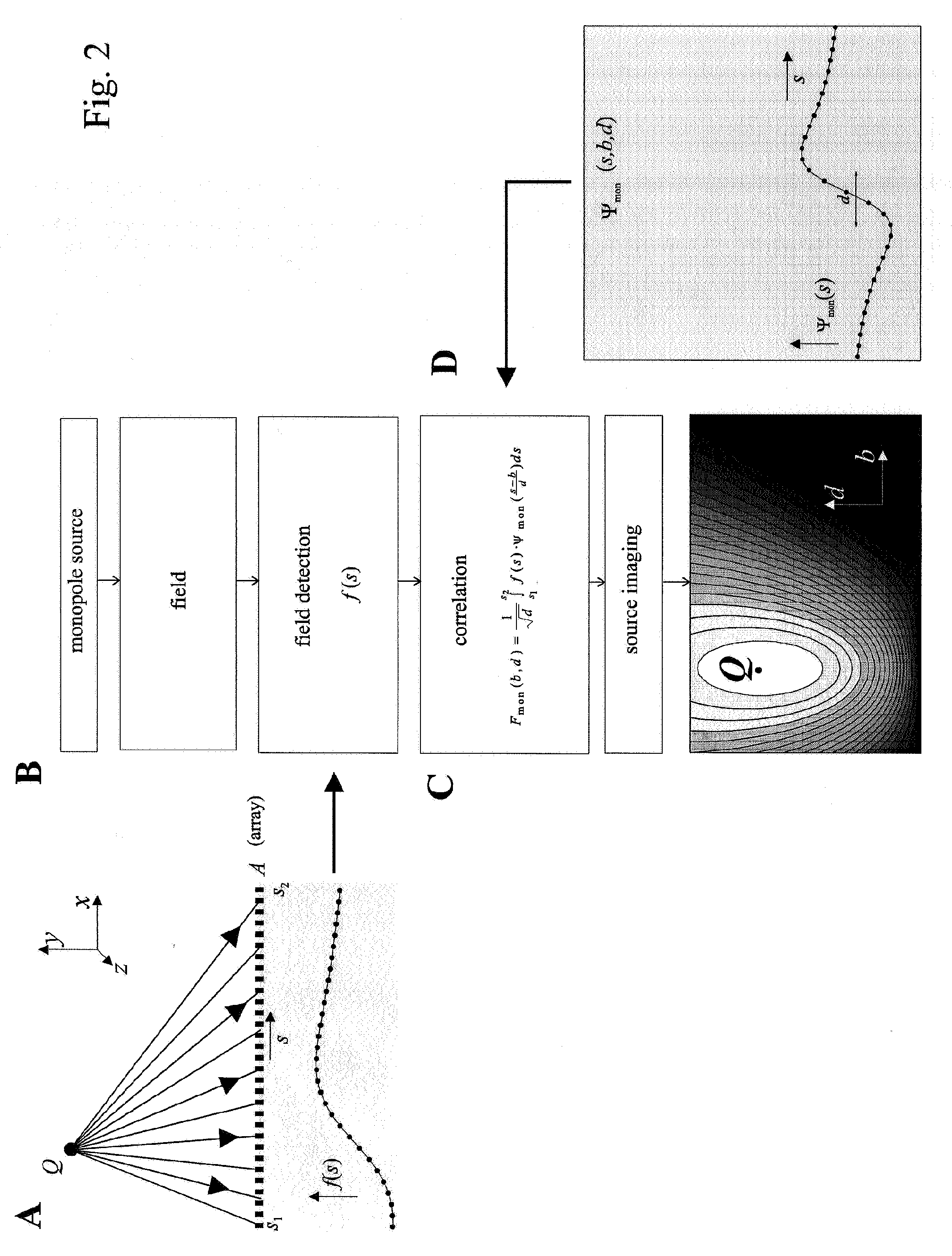
[0006]It has been found that a correlation of the observations of the sensors in the sensor array and a predetermined result derived for a (series of) template sources positioned at a predetermined position and / or a predetermined orientation with respect to said sensor array allows parameters, such as the position, to be estimated. It is further found that such a correlation also allows parameters of sources of a different type than a single dipole to be determined, such as monopoles, tripoles etc. and other sources, such as extended sources. Hence, such a system allows a larger variety of parameters of a larger variety of sources to be determined.

Problems solved by technology

However, a disadvantage of the prior art “Franosch” document is that the method can be used only if “a priori” knowledge is available on the existence of a single dipole source.
Hence, the method cannot be used to for example determine the positions and dipole moments of an unknown number of multiple sources.

Method used


Image

  • System and a method for determining one or more parameters of a source of a potential-energy field
  • System and a method for determining one or more parameters of a source of a potential-energy field
  • System and a method for determining one or more parameters of a source of a potential-energy field

Examples


Embodiment Construction

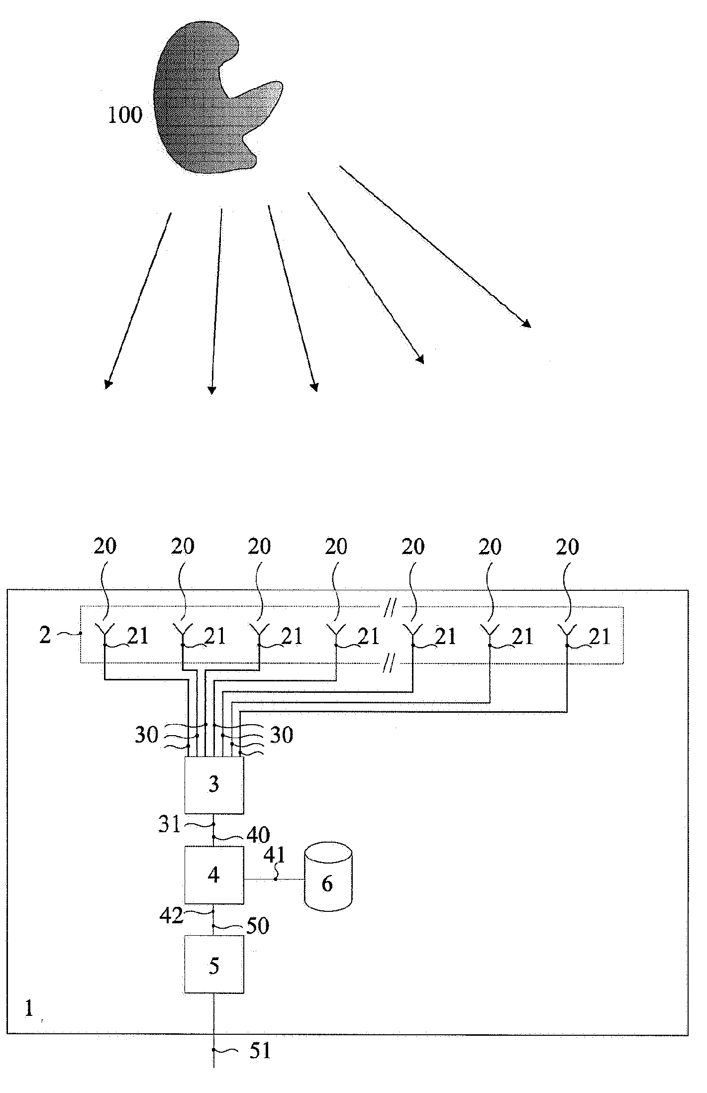
[0014]FIG. 1 schematically shows a block diagram of an example of an embodiment of a sensor system 1. The sensor system 1 includes an sensor array 2, a signal processor 3, a correlator 4 and a calculator 5.

[0015]A source 100 is shown in the vicinity of the sensor array 2. The source 100 generates a potential-energy field. The potential-energy field may be any suitable type of field. The potential-energy field may, for example, be an electric, (electro)magnetic, acoustic, pressure or other type of field.

[0016]The source may be any suitable type of source and may, for example, be one or more of: a monopole, a dipole, being constant, changing or vibrating, and may for instance be of an (electro)magnetic, electric, acoustic, and / or hydrodynamic nature. Also, as explained below in more detail, the source may be part of any suitable type of object, such as for instance the human brain, a vehicle, a vessel or otherwise. Furthermore, the source may be an extended source, i.e. a source which...


PUM


Abstract

A sensor system for determining parameters of a source of a potential-energy field. The system has a sensor array for sensing a property of the potential-energy field generated by the source, with a first sensor at a first position and a second sensor at a second position. The first and second sensor each have a sensor output for outputting a sensor signal representing the sensed property. A signal processor can determine the sensed property as a function of the position of the at least one first sensor and the at least one second sensor. A correlator is connected to the signal processor and arranged to correlate the determined result to a predetermined result derived for a template source positioned at a predetermined position and / or orientation with respect to the sensor array. A calculator is connected to the correlator. The calculator can determine the parameter from the correlation result.

Description

FIELD AND BACKGROUND OF THE INVENTION[0001]The invention relates to a system and a method for determining one or more parameters of a source of a potential-energy field.[0002]Systems for determining a parameter of a source, such as the distance or speed thereof, are known. For example, a passive sonar can receive acoustic waves emitted by a source and e.g. determine from the received acoustic waves the position and type of the source.[0003]From Franosch et al., “Estimating position and velocity of a submerged moving object by the clawed frog Xenopus and by fish—A cybernetic approach”, Biol Cybern (2005) 93: 231-238, a method is known for localizing a submerged moving sphere. The method includes an arrangement with a number of lateral line organs. Each of the lateral line organs has a number of sensors, the cupulae. The cupulae measure the local water velocity. The measured water velocities of each cupula are combined. By determining a position of the zeros and extrema of the combine...

Claims


Application Information

Patent Timeline
IPC IPC(8): G06F19/00G01R15/00A61B5/04A61B5/05
CPCG01D5/145
Inventor VAN NETTEN, SIETSE MARTEN
Owner UNIVERSITY OF GRONINGEN
Learn More