Smart keyless entry system
- Summary
- Abstract
- Description
- Claims
- Application Information
AI Technical Summary
Benefits of technology
Problems solved by technology
Method used
Image
Examples
embodiment 1
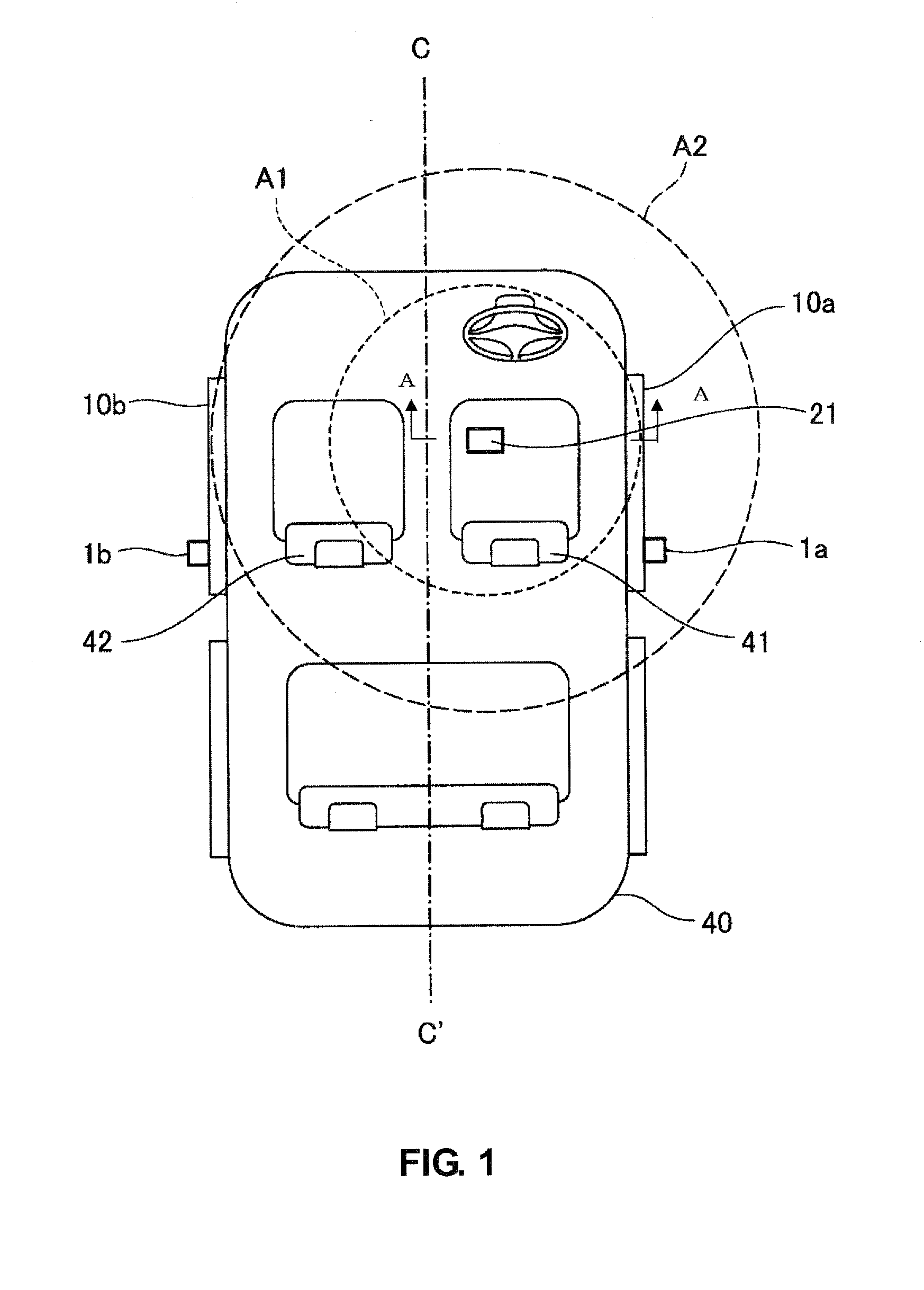
[0034]Hereinafter, a first embodiment of the smart keyless entry system of the present invention will be described. A basic concept of the present invention will be described referring to FIG. 1 in the first embodiment. FIG. 1, which is a schematic plan view of the vehicle compartment of the vehicle, shows the layout and the output range of a switching transmitting antenna of vehicle-inside transmitting antennas. FIG. 7 is a perspective view taken along line A-A of FIG. 1.
[0035]In the present embodiment, a vehicle-inside transmitting antenna 21 to transmit the request signal in the vehicle compartment is disposed below the driver's seat 41, which is off the center line C-C′ on the right side of the vehicle compartment. The vehicle-inside transmitting antenna 21 is fixed to a floor panel FP below the driver's seat 41 via a bracket BRK. The onboard device (not illustrated) is configured so as to switch the output strength of the request signal transmitted by the switching transmitter ...
embodiment 2
[0041]Next, the smart keyless entry system of a second embodiment of the present invention will be described. At first, the basic constitution of the smart keyless entry system according to the present invention will be described referring to FIG. 2. FIG. 2 is a block diagram to show the smart keyless entry system of the present embodiment.
[0042]As shown in FIG. 2, the smart keyless entry system of the present embodiment comprises the access switches 1a, 1b which are provided at outer faces of both-side doors of the vehicle, an onboard device 2 operative transmit the request signal of the LF band in response to operation of the access switches 1a, 1b, and the portable device 3 operative to transmit the receipt-acknowledgement signal of the UHF band in response to receiving the request signal. Herein, inFIG. 2, the access switch 1a provided at the outer face of the door on the side of the driver's seat is indicated as “right access switch,” and the access switch 1b provided at the ou...
PUM
 Abstract
Description
Claims
Application Information
 - R&D
- Intellectual Property
- Life Sciences
- Materials
- Tech Scout
- Unparalleled Data Quality
- Higher Quality Content
- 60% Fewer Hallucinations
Browse by: Latest US Patents, China's latest patents, Technical Efficacy Thesaurus, Application Domain, Technology Topic, Popular Technical Reports.
© 2025 PatSnap. All rights reserved.Legal|Privacy policy|Modern Slavery Act Transparency Statement|Sitemap|About US| Contact US: help@patsnap.com


