
Multiple energy inputs hydropower system

a hydropower system and energy input technology, applied in the field of power generation systems, can solve the problems of power loss, inundation of farmlands, and only about 50% of the installed capacity, and achieve the effect of reducing construction tim

Inactive Publication Date: 2009-06-18
CHING JOSE ONG
View PDF9 Cites 32 Cited by
  • Summary
  • Abstract
  • Description
  • Claims
  • Application Information

AI Technical Summary

Benefits of technology

[0024]Primarily, the present invention has incorporated a re-boosting pump (27) to re-boost and to supply additional pressure energy input to the system periodically. The re-boosting pump gets its energy from the starting / re-boosting generator (3). This works to keep the level of the energy output sustainable.
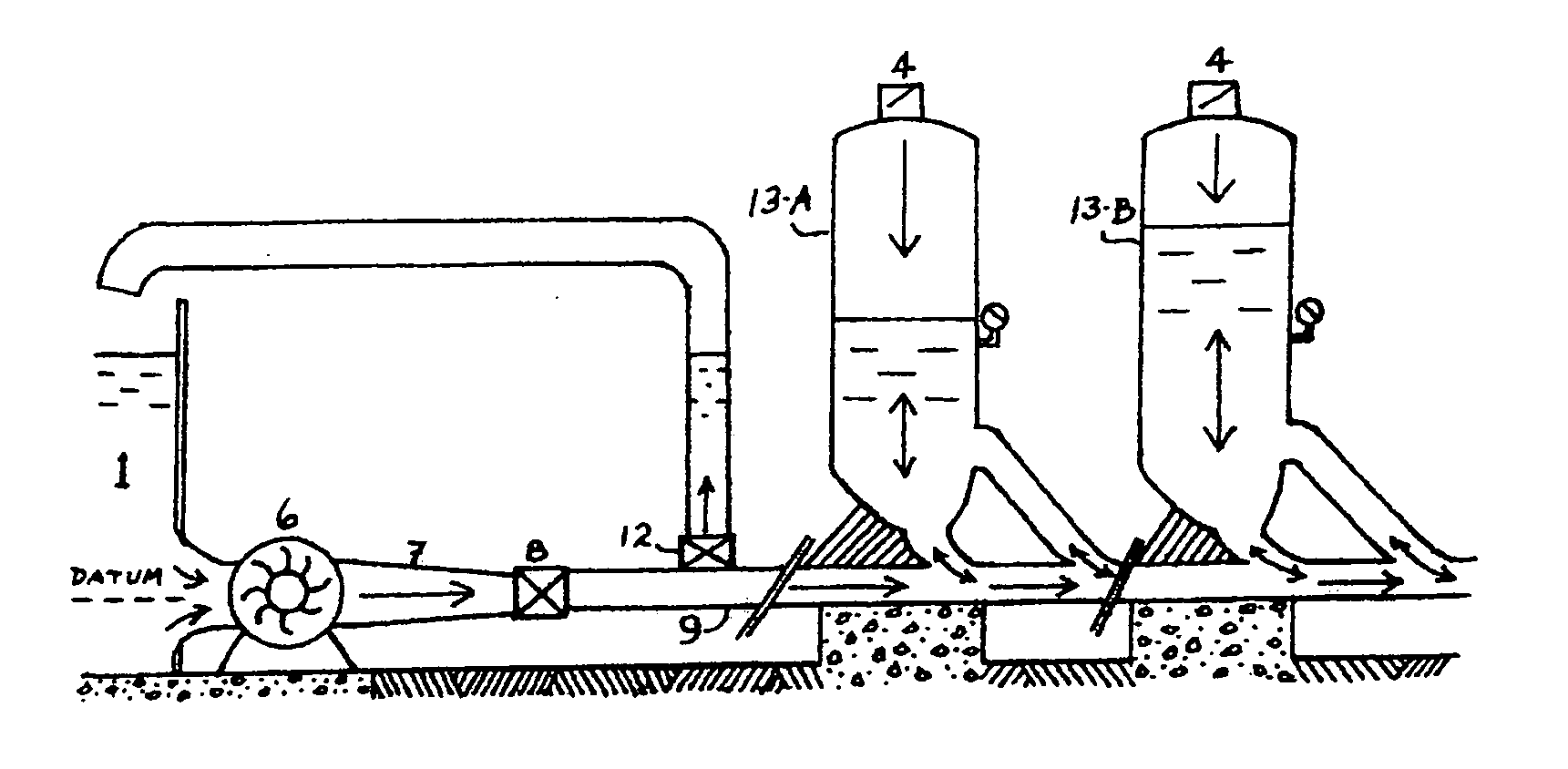
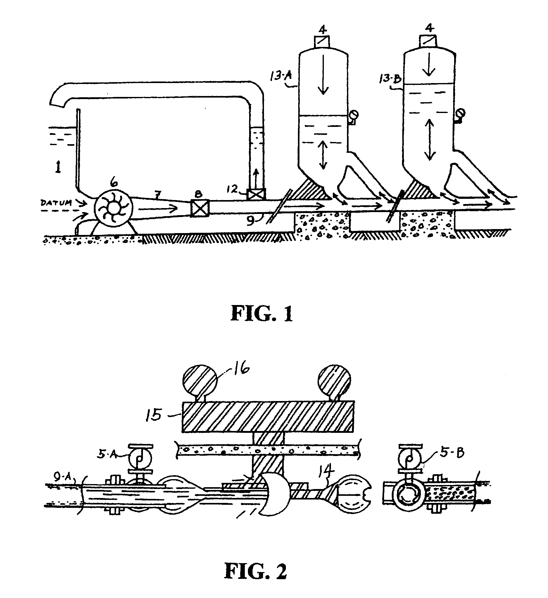
[0030]This system has a complementary sub-loop of re-circulating water path. When the spherical valve is opened rapidly, huge volume of high compressed water jets out of the main penstock, forming a low pressure vacuum upstream. The accompanied suction force would pull in water from the reservoir directly inot the main penstock through the vacuum suction pipes, bypassing the main pump. This operates as the high pressure energy is transformed into a low pressured vacuum condition forming suction force. This mechanisms of water transferring functions like an electric pump but without consuming any electric power. This works to stabilize the pressure and to increase significantly the volume of water in the main penstock. An auxiliary pump (24) sustains the pressure and the volume of water needed. The water jet impinges on the Pelton turbine generator to produce electric energy.
[0037]First, is uses controlled volume of water to generate power in a recycling mode, thus its utilization rate is much higher.

Problems solved by technology

First, it is available only to sites or areas where there are big natural waterways. These sites are usually found in far flung areas where the power transmission lines to the cities are not only expensive, but also cause power losses.
Second, its operation is entirely dependent on the seasonal precipitations, such that its average annual output is only about 50% of the installed capacity.
Third, building dams could inundate farmlands and it could carry heavy social costs.
Fourth, the construction time of a dam is very long.
Fifth, the required civil works are expensive.
Sixth, the continuous removing of the upstream debris is tedious maintenance work, and the sedimentation problem is always present.
And lastly, there is always the danger of dam failure that could result to catastrophic consequences to lives and properties.
Though this prior art has various input energy derived from erratic natural sources, such as winds, sunlight, waves, tidal changes, etc. and would therefore solves the low water level problem of the dam, the other inherent problems linked to the conventional hydro electric plant like the dependence to the annual precipitation and requirement of vast area, were not overcome.
Though the above prior art harnesses the renewable wave energy into useable electrical power to meet peak load periods, still it does not address the other inherent problems associated to the conventional hydroelectric power plant.

Method used


Image

  • Multiple energy inputs hydropower system
  • Multiple energy inputs hydropower system
  • Multiple energy inputs hydropower system

Examples


second embodiment

of the Present Invention

[0183]The present invention has a second embodiment as shown in FIG. 14 wherein the force of pressure head provided by the main pump (6) in FIG. 11 is being substituted by the force of elevation head from an upper reservoir (22) on top of a mountain plateau as shown in FIG. 14 ; the elevation head Z minus the down flow pipe frictional head loss is equal to the pressure head of the pump; while the other equipments and structures of the second embodiment system are identical in dimensions and functions to the first embodiment system as presented.

[0184]This second embodiment system has a motor pump (23) connected to the tail reservoir to deliver water from the lower level up to the upper reservoir (22) for re-circulation. It also has a low level reservoir similar to the main reservoir of the original embodiment outside the powerhouse to dissipate heat and to supply water to the vacuum suction pipes; auxiliary pump pipe line and re-boosting pipe line.

[0185]The tw...


PUM


Abstract

The present invention has incorporated a re-boosting pump to re-boost and to supply additional pressure energy input to a system periodically. The re-boosting pump gets its energy from a starting / re-boosting generator. This works to keep the level of the energy output sustainable.Another feature of the present invention is that it has incorporated a convergence recoil nozzle that utilizes a recoil force of the water jet. This recoil force which is equal in magnitude and opposite in direction, will push a piston that is inside a pressure chamber. This force is capable of doing different kinds of works, such as a pressurized liquid to add energy input to the system through a pressure pipe into the main penstock or it can be used as a pressure energy for the desalination of saline water.

Description

FIELD OF THE INVENTION[0001]The present invention relates in general to power generation system. More specifically, it relates to a multiple energy inputs hydropower system which synergistically harnesses the elevation head; the velocity head and the elastic potential energy of water to generate electric power.BACKGROUND OF THE INVENTION[0002]Force is defined as vector quantity that pushes or pulls a body or mass. It can be nature induced or machine induced. The unit of measure is in Newton (n). A force that produced displacement (m) constitute work (n×m). The applied force is proportional to the displacement produced. The bigger the force applied on a particular mass, the bigger would be the displacement.[0003]Mechanical energy is defined as a capacity to do work. It produces work which involves a quantity of force. Energy is expressed in terms of work; because work is also the measured amount of energy that is transferred. Both are measure in terms of joules or Newton-meter (n×m)....

Claims


Application Information

Patent Timeline
IPC IPC(8): F03B13/00F03B17/04
CPCF03B1/00F03B13/06F03B17/005F03G7/00Y02E60/17Y02E10/20Y02E10/22Y02E10/223F05B2240/2411Y02E60/16
Inventor CHING, JOSE ONG
Owner CHING JOSE ONG
Learn More