Method for fault location in electric power lines

a technology for fault location and electric power lines, applied in the direction of fault location, fault location by conductor type, instruments, etc., can solve the problems of mechanical damage which must be removed, slow method, and high cos

Active Publication Date: 2009-06-11
ABB POWER GRIDS SWITZERLAND AG
View PDF1 Cites 33 Cited by
  • Summary
  • Abstract
  • Description
  • Claims
  • Application Information

AI Technical Summary

Benefits of technology

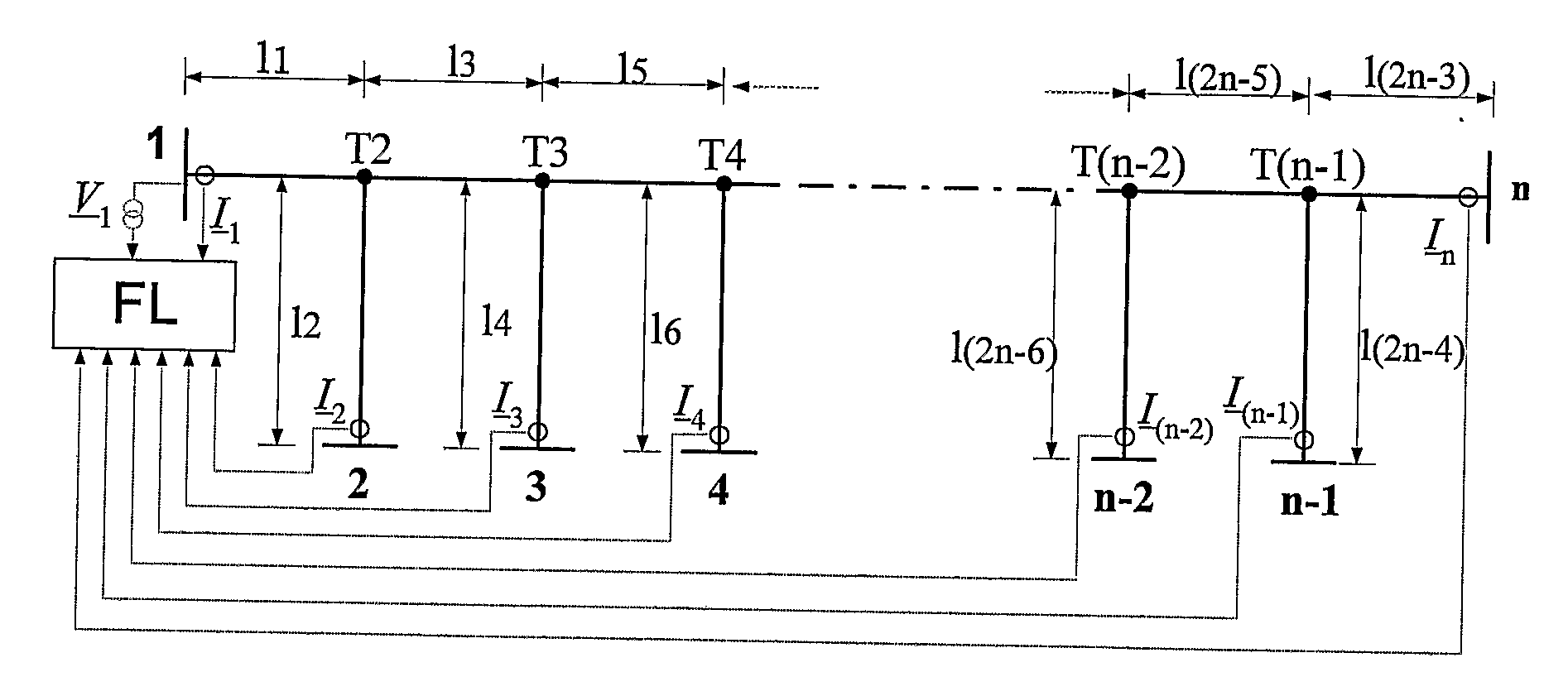
[0002]The accurate location of the fault in electric power lines is of great importance both for power companies dealing with electric energy distribution and for end users of electric energy. Quick and exact location of the fault point effects the quality of transmitted electric energy and its reliable and uninterrupted supply. In most cases, faults result in mechanical damage which must be removed before voltage is restored in the line. Quick rectification of a fault is possible if the place of the fault is known exactly. The simplest method for determining the location of a fault is searching along the line. This method is slow and expensive, even dangerous in adverse weather conditions. Fault locators facilitating quick determination of the fault point are used for locating fault points. A fault locator is usually a part of a digital protective relay located in power stations or substations. Depending on the type of electric power lines: parallel lines, three-terminal power lines, multiple-terminal power lines, and depending on the location of final terminals and the diversity of measuring signals, different ways of fault location are distinguished.
[0031]The advantage of the method for fault location in electric power lines which is the subject of this invention is that it makes it possible to determine the fault point for a transmission or distribution system both with passive and active tap (taps). Due to the required input signals, the inventive location method can be applied in differential-current protection, which will increase the functionality of the protective relay. In this way, the protective relay, besides its main feature, i.e. indication whether the fault occurred in the given protection zone or outside it, will be able to exactly define the location of the fault.

Problems solved by technology

In most cases, faults result in mechanical damage which must be removed before voltage is restored in the line.
This method is slow and expensive, even dangerous in adverse weather conditions.

Method used


Image

  • Method for fault location in electric power lines
  • Method for fault location in electric power lines
  • Method for fault location in electric power lines

Examples


Embodiment Construction

[0033]The method according to the present invention is explained in an embodiment shown in the drawing, where

[0034]FIG. 1 shows a general diagram of the electric network for the implementation of the inventive method for a three-terminal electric power line, with indicated sections LA, LB and LC,

[0035]FIG. 2—an equivalent circuit diagram for the positive sequence component for the assumption that the fault occurred in line section LA,

[0036]FIG. 3—an equivalent circuit diagram of a transmission system for the negative sequence component for the assumption that the fault occurred in line section LA,

[0037]FIG. 4—an equivalent circuit diagram of a transmission system for the zero sequence component for the assumption that the fault occurred in line section LA,

[0038]FIG. 5—an equivalent circuit diagram for the positive sequence component for the assumption that the fault occurred in line section LB,

[0039]FIG. 6—an equivalent circuit diagram of a transmission system for the negative seque...


PUM


Abstract

A method for locating faults in three-terminal and multi-terminal power lines, applicable in electric power systems for overhead and underground cable transmission and distribution lines. The inventive method is characterised in that it measures current for fault and pre-fault conditions and in one terminal station of the system line phase voltage for fault and pre-fault conditions is measured, a hypothetical fault location is assumed, the distances to the hypothetical fault locations are calculated and fault resistance is calculated, the actual fault point is selected by first comparing the numerical values concerning the distances to the hypothetical fault locations and rejecting those results whose numerical values are negative or bigger than one in relative units, and then by analysing the values of the calculated fault resistances for the fault locations and rejecting those results of the calculations for which the value of fault resistance is negative, and if there is still more than one calculation result remains not rejected then performing selection of the valid result by analysing the values of the calculated respective equivalent source impedances.

Description

[0001]The present invention is concerned with a method for fault location in electric power lines applicable both to three-terminal power lines and multiple-terminal power lines, fit to be used in the power industry for overhead and overhead-cable transmission or distribution lines.[0002]The accurate location of the fault in electric power lines is of great importance both for power companies dealing with electric energy distribution and for end users of electric energy. Quick and exact location of the fault point effects the quality of transmitted electric energy and its reliable and uninterrupted supply. In most cases, faults result in mechanical damage which must be removed before voltage is restored in the line. Quick rectification of a fault is possible if the place of the fault is known exactly. The simplest method for determining the location of a fault is searching along the line. This method is slow and expensive, even dangerous in adverse weather conditions. Fault locators...

Claims


Application Information

Patent Timeline
IPC IPC(8): G01R31/08
CPCG01R31/086G01R31/088
Inventor BALCEREK, PRZEMYSLAWFULCZYK, MAREKROSOLOWSKI, EUGENIUSZIZYKOWSKI, JANSAHA, MURARI
Owner ABB POWER GRIDS SWITZERLAND AG
Why Eureka
Try Eureka