
Color-coded target, color code extracting device, and three-dimensional measuring system

Active Publication Date: 2009-06-11
KK TOPCON
View PDF21 Cites 37 Cited by
  • Summary
  • Abstract
  • Description
  • Claims
  • Application Information

AI Technical Summary

Benefits of technology

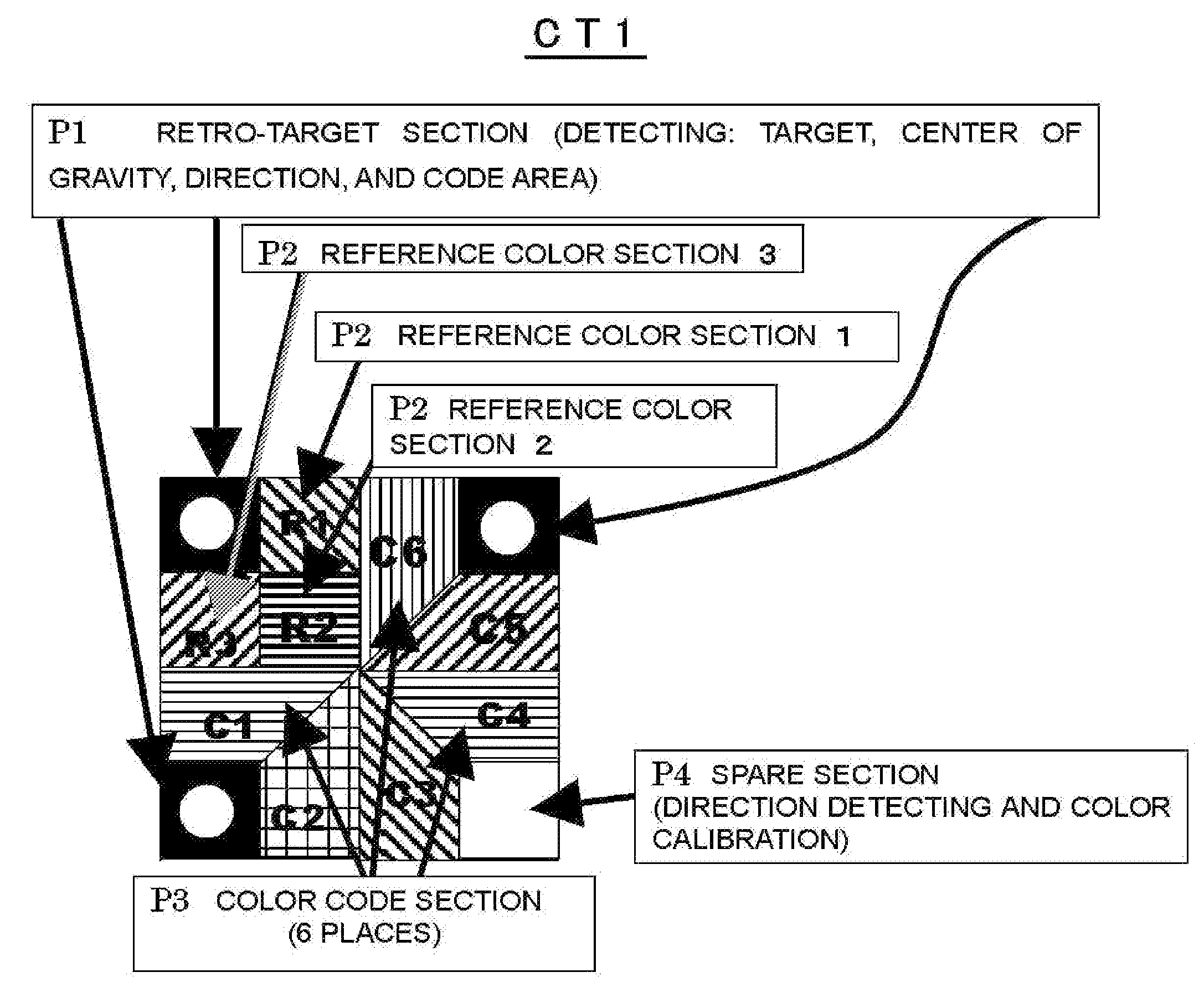
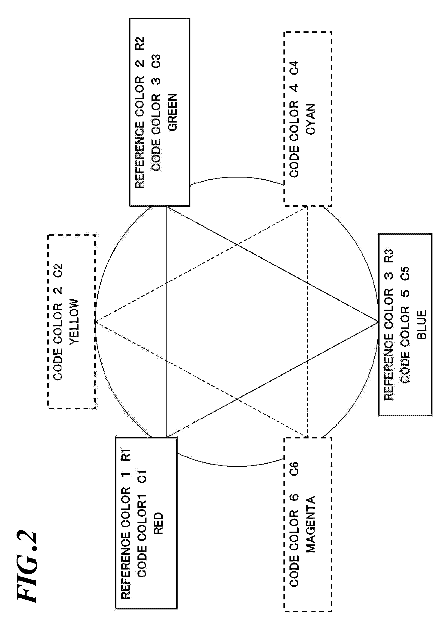
[0011]Here, the target represents typically a target for three-dimensional measurement. However, the target is not limited to that but includes targets for discriminating commodities, cargo, samples, etc. The HSI space is to express a color using a coordinate (HSI) system using hue (H), saturation (S), and intensity (I) as variables. The coordinate system is typically cylindrical, with the circumferential direction representing hue (H); the radial direction, saturation (S); and the height direction, intensity (I). With such a constitution, as one color is different from an adjacent color by a certain value equal to or more than the specific value, the adjacent colors are easy to discriminate each other. Thus, it is possible to provide a color-coded target having a color code of colors chosen less likely to cause incorrect reading of the code.
[0030]This invention makes it possible to provide a color-coded target having a code of colors chosen to minimize code reading errors and to provide a technique for automatically detecting and processing the target.

Problems solved by technology

When the number of images taken increases, there arises a problem that the amount of manual identification work becomes great and the work takes much time.
However, a problem has been left unsolved on how to choose the color of the color-coded target.
If a color code is read incorrectly and as a result a wrong position is determined to be an identical position for the target position, a great amount of time is required to find out the incorrectly determined position and correct it.

Method used


Image

  • Color-coded target, color code extracting device, and three-dimensional measuring system
  • Color-coded target, color code extracting device, and three-dimensional measuring system
  • Color-coded target, color code extracting device, and three-dimensional measuring system

Examples


second embodiment

[0122]FIG. 13 shows an example of a color-coded target CT2 as the second embodiment. In the color-coded target CT2 shown in FIG. 13, the color code section P3 is configured with 9 unit areas of a small square shape. In other words, a square color-coded target CT2 is divided into 16 pieces of 1 / 16 square with three vertical lines and three horizontal lines. The reference color section P2 is made with the same disposition as the color-coded target CT1, and the color-coded section is configured with 9 equal-sized 1 / 16 squares. The retro-target section P1 and the spare section P4 are the same as those of the color-coded target CT1. When the number of colors in this embodiment is made to be 9, the number of codes is the factorial of 9, or 362880, or the number of codes that can be expressed.

[0123]FIG. 14 shows disposition of reference colors and code colors on the hue circle of the second embodiment. For example, colors in the unit areas R1-R3 of the reference color section are made red,...

third embodiment

[0126]FIG. 17 shows an example of a color-coded target CT3 of the third embodiment; an example containing reference colors other than the three primaries of light. On the hue circle of code colors in the HSI color space, 4 reference colors (R1-R4), and 8 code colors including reference colors (C1-C8) are employed, with hues (angles) of adjacent code colors at even intervals. While the number and shapes of all the unit areas of both the reference color section P2 and the color code section P3 are the same as those in the second embodiment, the number of the unit areas of the reference color section P2 is 4 disposed in a space between two retro-targets P1; and the number of unit areas of the color code section P3 is 8 disposed in positions other than the position section of the retro-targets P1, the reference color code section P2, and the spare section P4.

[0127]FIG. 18 shows the disposition of reference colors and code colors on the hue circle of the third embodiment. On the hue circ...

fourth embodiment

[0128]FIG. 19 shows an example of color-coded target CT4 of the fourth embodiment. The number of reference colors is made to be 2 (R1 and R2), and the number of code colors is made to be 4 (C1-C4) including the reference colors. In this example, hues (angles) of adjacent code colors are disposed at even intervals. The color-coded target CT4 is divided into two; an upper left portion and a lower right portion. Each portion, excluding the retro-target section P1 and the spare section P4, is made to be a reference color section P2 and a code color section P3. In the case a condition is given that the number of colors used is 4, or 2 reference colors plus intermediate colors between the two adjacent reference colors, 24 (4×3×2×1) kinds of codes may be expressed. In this embodiment, the reference color area R2 of the color-coded target CT1 is divided into two with a straight line interconnecting the center of the CT1 and the lower right apex of the retro-target section P1. One of the div...


PUM


Abstract

To provide a color-coded target having a color code of colors chosen not to cause code reading errors and technique for automatically detecting and processing the targets. The color-coded target CT1 of this invention includes, on its surface: a position detecting pattern P1 indicating a position to be measured; a reference color pattern P2 having a plurality of unit areas tinted in different colors for use as color references; and a color code pattern P3 having a plurality of unit areas tinted in different colors for discriminating the targets. The colors of the color code pattern P3 are chosen so that adjacent colors in the HSI color space are different in at least one of hue, saturation, and intensity by a specified value or greater.

Description

BACKGROUND OF THE INVENTION[0001]1. Technical Field[0002]This invention relates to a color-coded target, a color code extracting device, and a three-dimensional measuring system. More specifically, this invention relates to a color-coded target having codes with the colors thereof chosen so as not to cause code reading errors, a color code extracting device for automatically detecting the codes, and a three-dimensional measuring system for measuring three-dimensional coordinates using the color code extracting device.[0003]2. Related Art[0004]The three-dimensional image measurement is a method of determining three-dimensional coordinates of an object to be measured using images taken from different directions. In such a method, an identification work is required to determine the same position in a number of images taken from different directions. When the number of images taken increases, there arises a problem that the amount of manual identification work becomes great and the work...

Claims


Application Information

Patent Timeline
IPC IPC(8): G06K9/00
CPCG01C15/02
Inventor MORIYAMA, TAKUYAKOCHI, NOBUO
Owner KK TOPCON
Learn More