
Method of quantum cryptography using blind photon polarization quibits with multiple stages

a quantum cryptography and blind photon polarization technology, applied in the field of quantum cryptography, can solve the problems of easy acquisition of information by a third party, risk exposure of conventional cryptographic systems based on mathematical methods, and inability to correct or correct decryption

Active Publication Date: 2009-06-11
PAICHAI UNIV IND ACADEMIC COOPERATION FOUND
View PDF1 Cites 8 Cited by
  • Summary
  • Abstract
  • Description
  • Claims
  • Application Information

AI Technical Summary

Benefits of technology

[0036]The present invention provides a quantum cryptography method of rotating the polarization of photon fluxes using two or more photon fluxes and transmitting them at transmission and reception steps as described above, thereby being safe against all attacks on quantum encrypted information, such as beam-splitting attacks, impersonation attacks, or Trojan Horse attacks, unlike the conventional quantum cryptography method.

Problems solved by technology

The reason for this is that conventional cryptographic systems are established using mathematical methods, but, with the development of quantum computers, conventional cryptographic systems based on mathematical methods are starting to be exposed to risk, and thus a cryptographic system using the quantum phenomena of physics can be the alternative to them.
As a result, the results of decryption may be correct or incorrect.
In the above-described conventional quantum cryptography method using a photon flux, there is a problem in that information is easily acquired by a third party.
Furthermore, since the conventional technology uses one photon flux, information may leak.
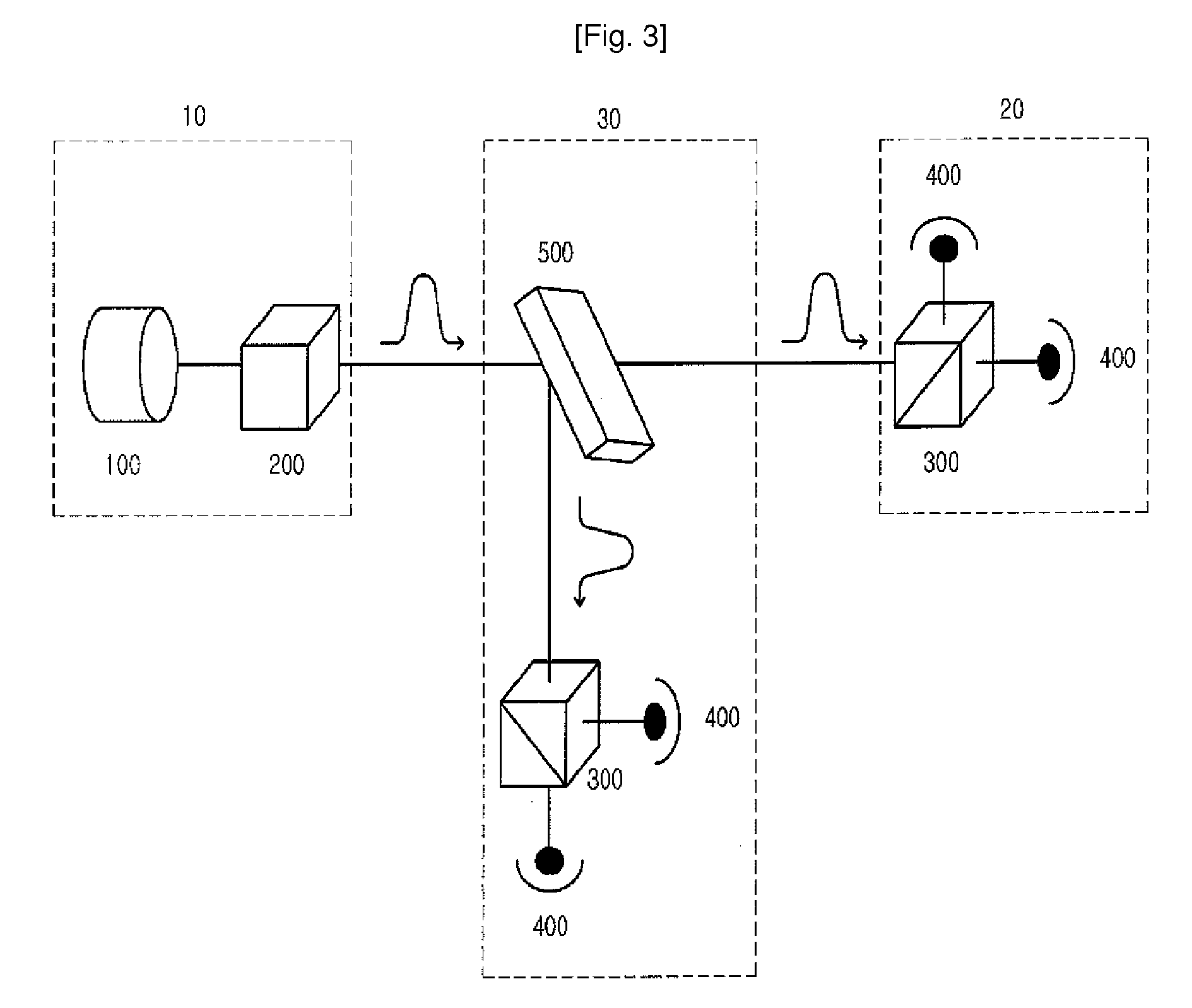
As described above, the quantum cryptography method using the conventional technology has a problem in that it is vulnerable to outside attacks, such as a beam-splitting attack or an impersonation attack.

Method used


Image

  • Method of quantum cryptography using blind photon polarization quibits with multiple stages
  • Method of quantum cryptography using blind photon polarization quibits with multiple stages
  • Method of quantum cryptography using blind photon polarization quibits with multiple stages

Examples


Embodiment Construction

[0043]Several embodiments of the present invention are described in detail with reference to the drawings below.

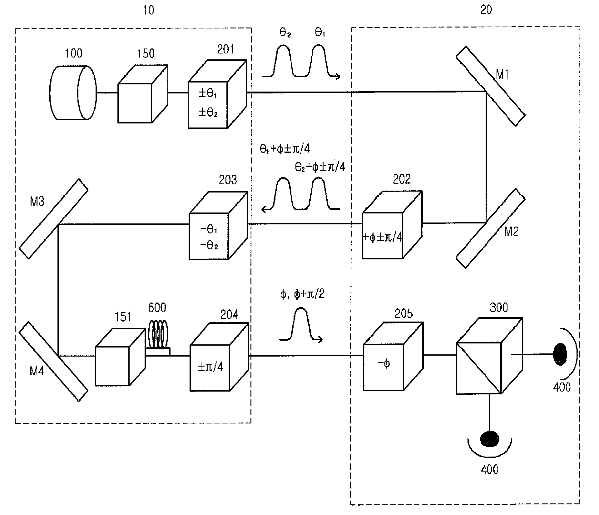
[0044]FIG. 4 illustrates a quantum cryptography method using a photon flux having irregular polarization in three stages. With reference to FIG. 4, the quantum cryptography method is described below, with it being divided into three states depending on the change of polarization. At a first step, the transmitter 10 selects an arbitrary angle θ for polarization, rotates a photon flux emitted from a light source 100 by the certain angle θ to prevent a third party from determining the polarization angle, and transmits it to a receiver 20. The photon flux passes through an optical switch 150 and is polarized at the angle θ through a polarization rotator 201.

[0045]At a second step, the receiver 20 again rotates the photon flux polarized at the angle θ, which is received from the transmitter 10, by a predetermined angle φ through a polarization rotator 202, and then transmits th...


PUM


Abstract

A cryptography method using a quantum phenomenon, which performs a multi-staged polarization process between a transmitter and a receiver to prevent a third party from knowing the polarization value of a photon. A transmitter rotates a photon flux by arbitrary angle θ and transmits it to a receiver. The receiver rotates the received photon flux by arbitrary angle φ and transmits it to the transmitter. The transmitter rotates the received photon flux by the reverse angle −θ of an angle, by which the transmitter 10 rotated it, then rotates it by polarization corresponding to an information bit, and transmits it to the receiver which rotates the received photon flux by the reverse angle −φ of an angle, and measures the polarization of the photon flux corresponding to the information bit, and recovers the information bit transmitted by the transmitter. Cryptography information may be transmitted using a plurality of photon fluxes.

Description

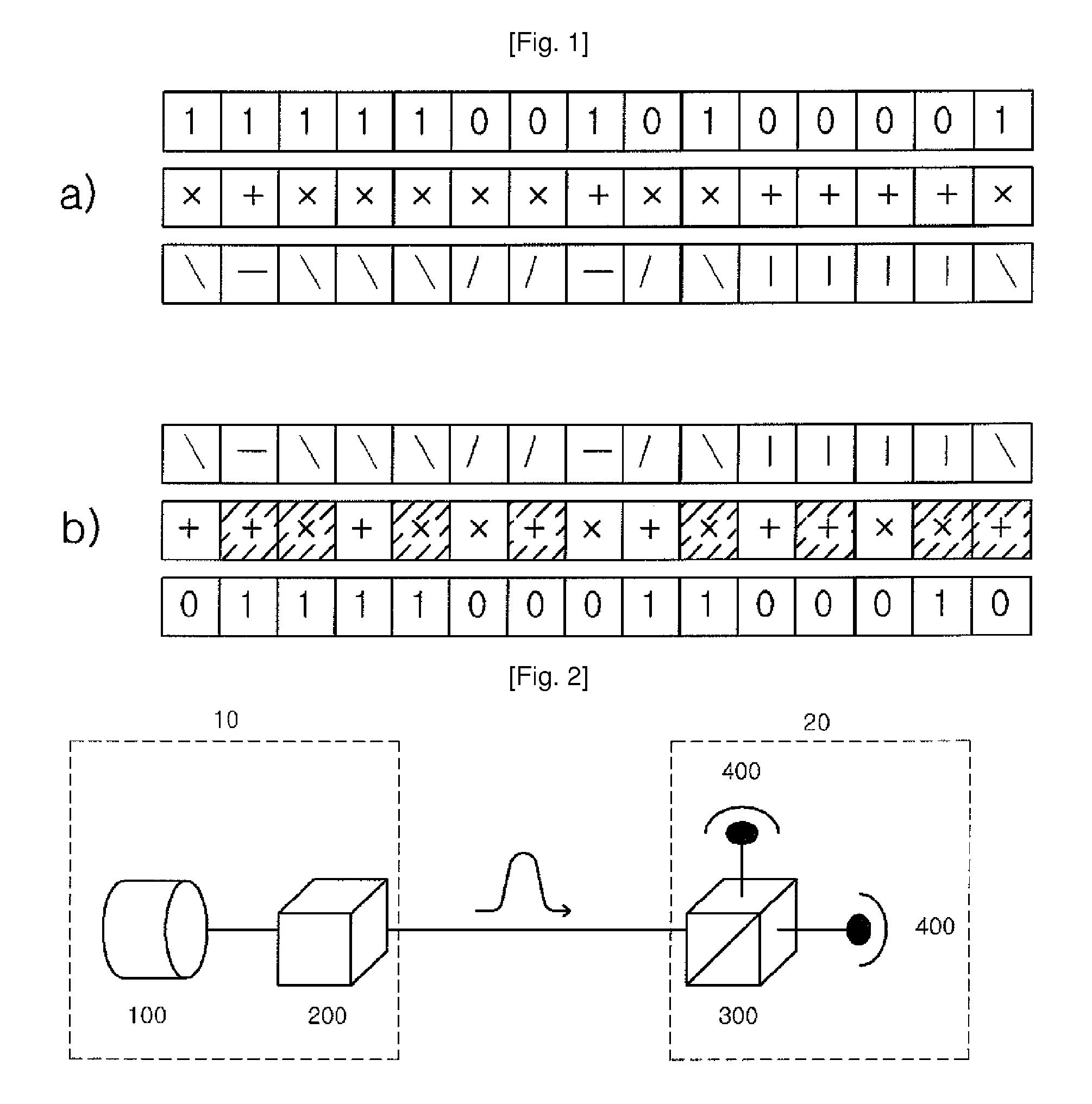
TECHNICAL FIELD[0001]The present invention relates to a cryptography method using a quantum phenomenon and, more particularly, to a quantum cryptography method which performs a multi-staged polarization process between a transmitter and a receiver in order to prevent a third party from knowing the polarization value of a photon.BACKGROUND ART[0002]Light energy, the frequency of which is ν, is given as an integer multiple of hν (where h is Planck's constant). When the value of a certain physical quantity is given as an integer multiple of a basic quantity (unit quantity), the basic quantity is called a quantum. That is, hν is a quantum. Furthermore, a quantum in the optical energy range is particularly called a photon.[0003]Recently, a cryptography method using a quantum phenomenon started to be researched. The reason for this is that conventional cryptographic systems are established using mathematical methods, but, with the development of quantum computers, conventional cryptograph...

Claims


Application Information

Patent Timeline
IPC IPC(8): H04L9/00H04L9/06
CPCH04L9/0858H04L9/08
Inventor KIM, CHIL-MINKYE, WON-HOPARK, YOUNG-JAI
Owner PAICHAI UNIV IND ACADEMIC COOPERATION FOUND
Learn More