
Camera control apparatus, camera control method, and camera system

a camera control and camera control technology, applied in the field of image processing techniques, can solve the problems of inability to correct, user may feel unnatural, and affect operability, so as to reduce color reproducibility differences and eliminate unnatural feeling of user

Active Publication Date: 2009-06-11
CANON KK
View PDF7 Cites 44 Cited by
  • Summary
  • Abstract
  • Description
  • Claims
  • Application Information

AI Technical Summary

Benefits of technology

[0014]The present invention has been made in consideration of the aforementioned problems, and attains a technique which can eliminate unnatural feeling of the user by reducing color reproducibility differences among a plurality of images sensed by a plurality of cameras when these images are simultaneously displayed on a display apparatus.
[0015]The present invention attains a technique which improves operability upon setting a reference candidate region for color adjustment.
[0019]According to the present invention, upon simultaneously displaying images sensed by a plurality of cameras on a display apparatus, color reproducibility differences among images are reduced, thus eliminating the user's feeling of unnaturalness.
[0020]Also, the operability upon setting a reference candidate region for color adjustment can be improved.

Problems solved by technology

However, when a plurality of sensed images of respective cameras are simultaneously displayed parallel to each other, the user may feel unnatural due to differences of color reproducibility among the plurality of cameras.
When the user arbitrarily determines white for different objects in place of an identical object to fail color adjustment of those objects, and arranges a plurality of cameras which do not sense an identical object, correction cannot be made.
In Japanese Patent Laid-Open No. 2004-221637, since priority levels of extracted candidate regions are displayed, when numbers indicating the priority levels of candidate regions, frames, and the like are simultaneously displayed on a single screen, the user hardly visually recognizes the color of a desired region, thus impairing operability.
When the priority numbers of regions, frames, and the like are merely displayed on the single screen at the same time, it is difficult for the user to compare the colors of a plurality of regions.
Hence, the operability upon region settings often impairs.
Also, when a plurality of images received from a plurality of cameras are displayed on a single screen via a network, the number of candidate regions to be displayed becomes large, thus further impairing the operability.

Method used


Image

  • Camera control apparatus, camera control method, and camera system
  • Camera control apparatus, camera control method, and camera system
  • Camera control apparatus, camera control method, and camera system

Examples


second embodiment

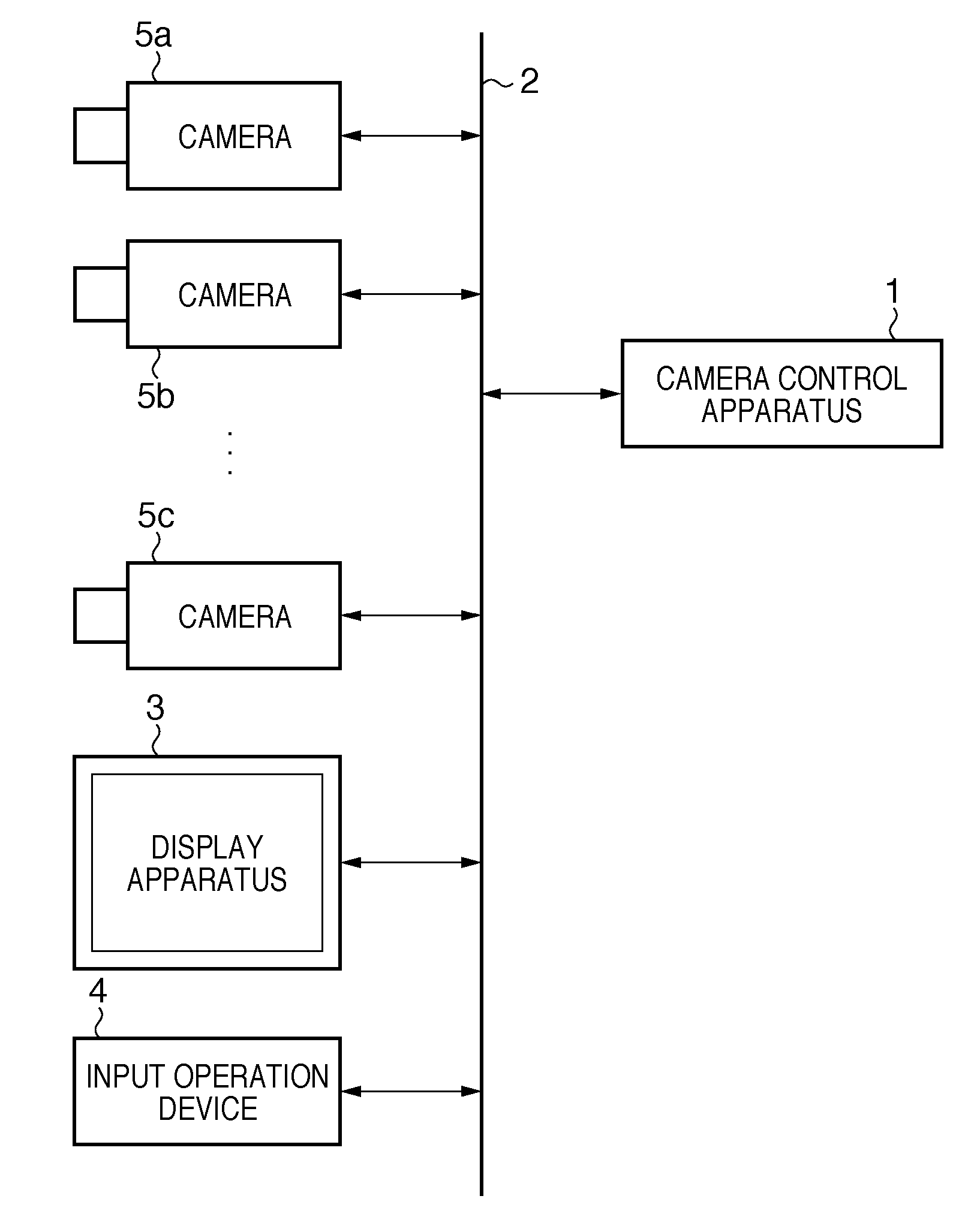
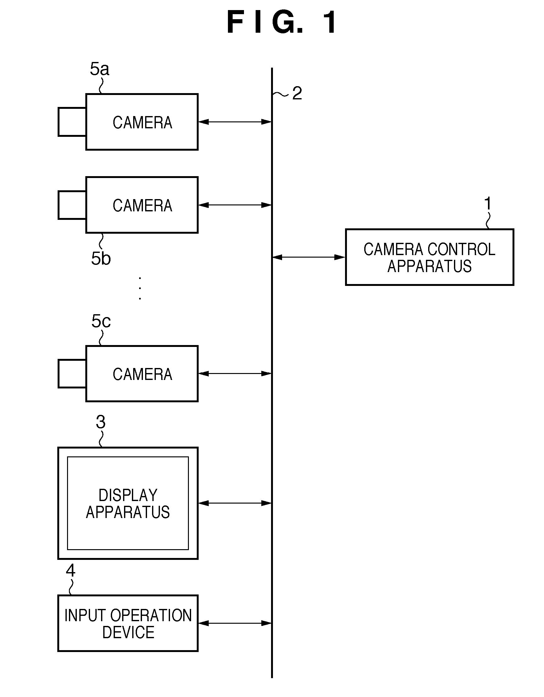
[0114]In the system of the second embodiment, the display apparatus 3 and input operation device 4 are excluded from the arrangement of FIG. 1, as shown in FIG. 6, and a camera control apparatus 1 incorporates a display unit 15 and input unit 16 instead, as shown in FIG. 7.

[0115]The display unit 15 is a display device such as a CRT, LCD, or the like, and displays images received from other cameras, a user interface (UI) screen (to be described later) of the camera control apparatus 1, and the like.

[0116]The input unit 16 may be implemented by a keyboard, buttons, mouse, and the like, or may be implemented by a touch panel and may be integrated with the display unit 15.

[0117]The user visually confirms images which are sensed by cameras 5a to 5c and are displayed on the display unit 15, and transmits a camera designation command by operating the input unit 16. Also, the user visually confirms images which are sensed by the cameras 5a to 5c and are displayed on the display unit 15, and...

first embodiment

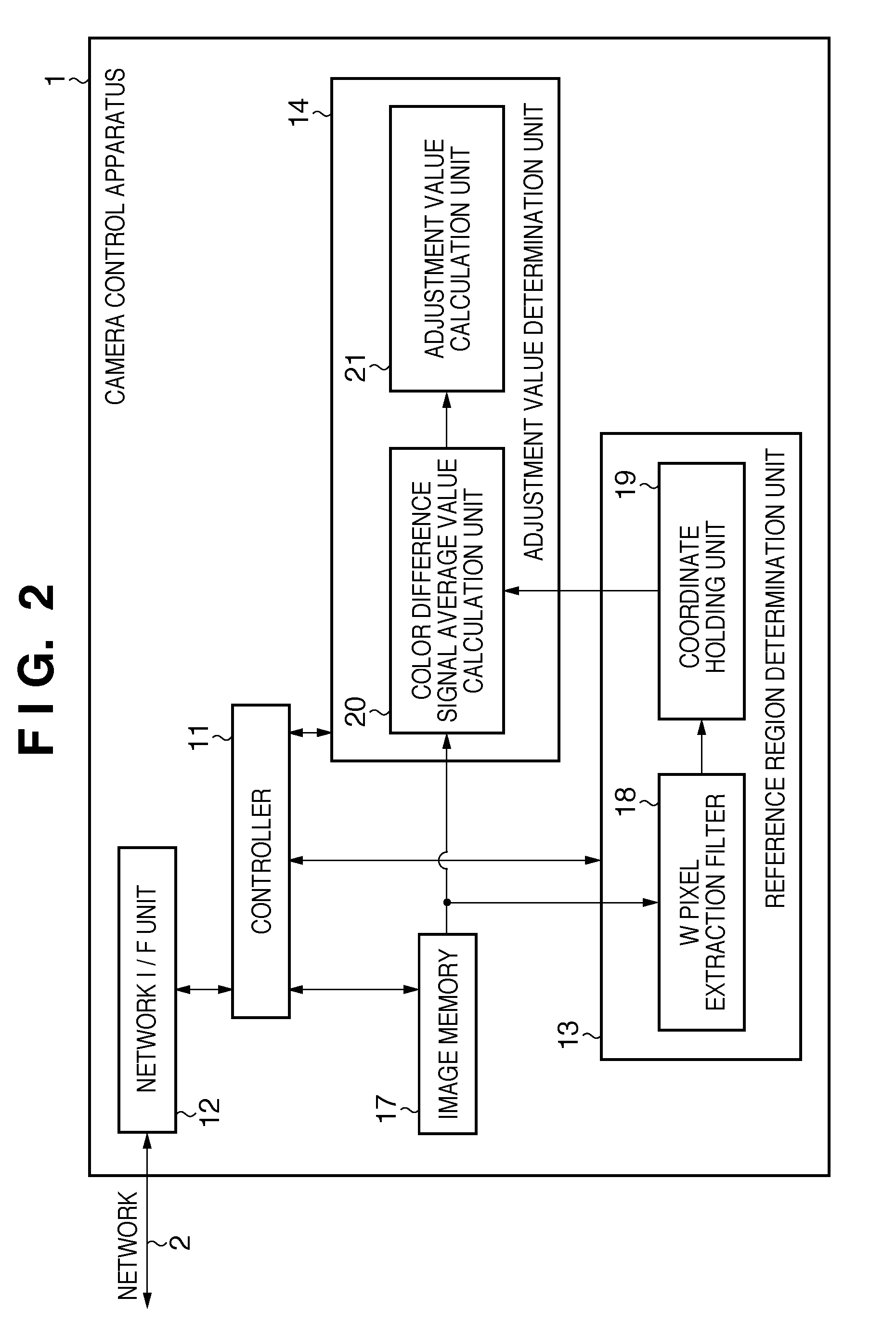
[0118]The arrangements and operations of a reference region determination unit 13, an adjustment value determination unit 14, and the cameras 5a to 5c are as described in the

[0119]As described above, even when the display unit and input unit are incorporated in the camera control apparatus 1, the same effects as in the first embodiment can be provided.

[0120]A third embodiment of the present invention will be described below referring to the drawings. The present invention can also be achieved when a computer program that implements the functions of the first and second embodiments is directly or remotely supplied to a system or apparatus. In this case, a program code itself read out from a storage medium implements the functions of the aforementioned embodiments, and the storage medium storing that program code constitutes the present invention.

[0121]FIG. 8 shows an example of a system or apparatus which reads out and executes the program code stored in the storage medium.

[0122]A co...

seventh embodiment

[0206]In the seventh embodiment, images displayed on the screen of FIG. 17 are output from the cameras allocated outdoors. However, when images from the cameras allocated outdoors and videos from those allocated indoors are displayed together on the screen of FIG. 17, since the color temperatures around the cameras are extremely different, trouble may occur in the WB control.

[0207]In such case, information associated with the color temperatures around the cameras is received from the respective cameras in step S402. In place of the information associated with the color temperatures, information associated with illuminances around the cameras may be used. If the illuminance is high, the probability of the outdoor camera is high, it is estimated that the color temperature is high. Conversely, if the illuminance is low, it is estimated that the probability of the indoor camera is high. The illuminance is determined by the aperture value, shutter speed (exposure time), gain, and the lik...


PUM


Abstract

A camera control apparatus comprises a processor adapted to control a display to display a plurality of sensed images respectively obtained from a plurality of cameras and a transmitter adapted to transmit a command to control another camera to execute color adjustment based on an image signal of a reference region of an image of a reference camera of the images displayed as a list by the processor.

Description

BACKGROUND OF THE INVENTION[0001]1. Field of the Invention[0002]The present invention relates to an image processing technique for displaying images of a plurality of cameras connected via a network.[0003]2. Description of the Related Art[0004]Conventionally, a camera system which simultaneously displays, on a display apparatus, a plurality of still images and movies (to be referred to as images hereinafter) sensed by a plurality of digital still cameras and digital video cameras (to be referred to as cameras hereinafter) connected via a network is available. In this camera system, each individual camera executes auto white balance (AWB) control and the like of a sensed image.[0005]The AWB processing detects a white (achromatic) part of image data obtained by an image sensing element, and calculates a color temperature of an illumination light source with respect to an object in a sensed image based on the detection result (white part). Then, the processing multiplies image data obt...

Claims


Application Information

Patent Timeline
IPC IPC(8): H04N9/73H04N5/228
CPCH04N5/222H04N5/23206H04N9/735H04N9/68H04N5/247H04N23/661H04N23/631H04N23/90H04N23/88
Inventor NAGAMASA, YOSHINOBUMASAKI, JUNYAFUKUI, TOSHIYUKIASAI, HIROKI
Owner CANON KK
Learn More