
Method and apparatus for transporting a product within a diffuser

a technology of diffuser and product, which is applied in the directions of liquid dispensing, food preparation, food science, etc., can solve the problems of limiting the maximum throughput capacity of the diffuser that can be economically constructed, less than 50% of the costly chain-slat assembly or screen deck is usefully working, and the size and cost of the bridge structure is rapidly increased

Inactive Publication Date: 2009-06-11
BOSCH PROJECTS
View PDF26 Cites 3 Cited by
  • Summary
  • Abstract
  • Description
  • Claims
  • Application Information

AI Technical Summary

Benefits of technology

[0048]Preferably the apparatus includes a control system arranged to control the first and second drive means so that a minority of the plurality of transport zones is moved towards the inlet of the diffuser, while the majority of the plurality of transport zones are moved towards the outlet.
[0049]The first and second drive means and / or the control system may be arranged so that the second speed of the plurality of transport zones is three or more times faster than the first speed of the plurality of transport zones. Preferably the first and second drive means and / or the control system may be arranged so that the second speed of the plurality of transport zones is six to fifteen times faster than the first speed of the plurality of transport zones.

Problems solved by technology

In fixed screen deck diffusers, the bed is dragged forward by slats suspended between a series of chains, driven by sprockets mounted on a single long and costly rotating headshaft.
Practical disadvantages of these methods are that less than 50% of the costly chain-slat assembly or screen deck is usefully working at any time.
The size and cost of the bridge structures escalates rapidly with the width to be spanned.
This limits the maximum throughput capacity of diffusers that can be economically constructed.
Moving components of both systems are highly stressed and costly to maintain.

Method used


Image

  • Method and apparatus for transporting a product within a diffuser
  • Method and apparatus for transporting a product within a diffuser
  • Method and apparatus for transporting a product within a diffuser

Examples


second embodiment

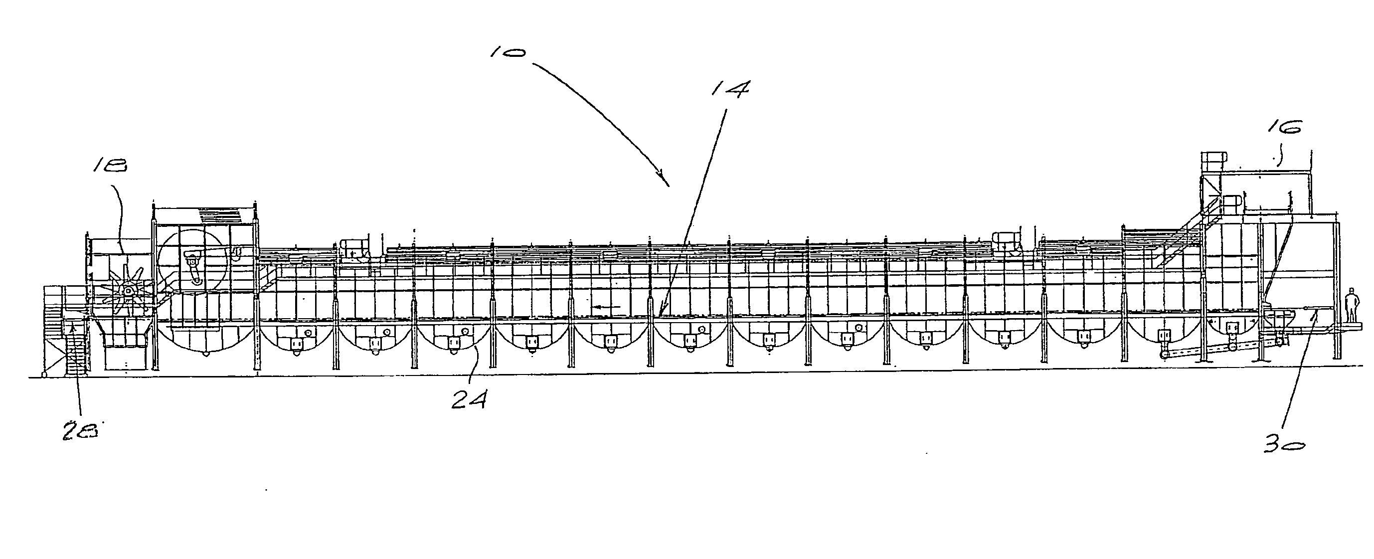
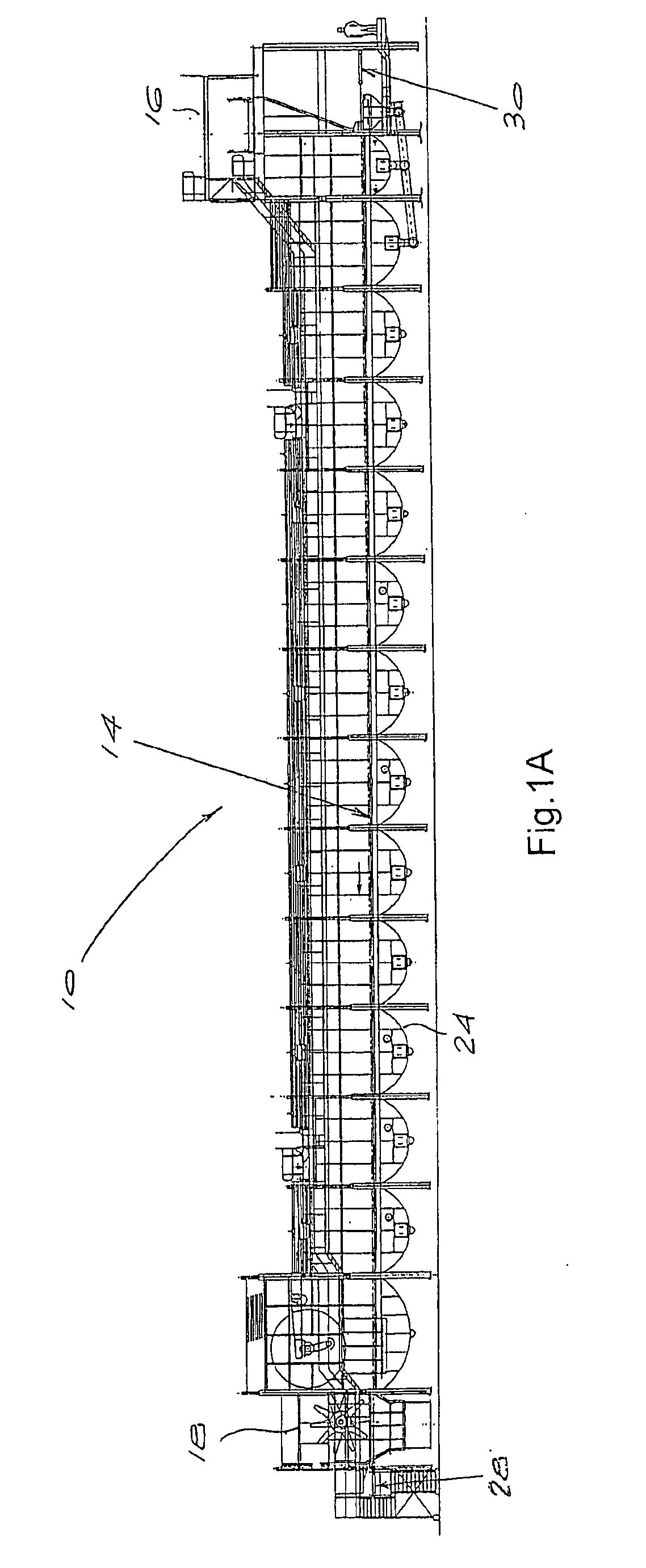
[0078]FIG. 4 shows the transport apparatus, as also applied to the moving deck type diffuser, comprising an arrangement wherein the movement of the deck 50 is articulated. FIG. 5 depicts part of one longitudinal transport zone. The portions of the deck making up each transport zone are raised slightly on the forward stroke and / or lowered on the return stroke, as shown by arrow 52. The transport zones comprise transport members in the form of deck sections 54 that are carried on sets of articulated supporting columns 56 that provide a rocking motion in which the screen zones are lifted on the forward stroke 58 and lowered on the return stroke.

[0079]In other embodiments of the invention, each longitudinal screen decked transport zone 26 which may include a plurality of transversely extending transport members, and which may further have the transversely extending transport members attached, above a fixed screen deck, to longitudinal driving members 70, 80, 90 or 100, as shown in FIGS....

third embodiment

[0082]Turning to FIG. 6, the transport apparatus according to the invention is shown. This embodiment has a ladder structure with each end of the transversely extending transport members 74 being attached to adjacent longitudinal driving members 70. The bed in each zone 72 is carried between two adjacent longitudinal driving members 70, which are drawn forward towards the outlet and then retracted together towards the inlet.

[0083]As with many of the other embodiments of the transporting mechanism, the transport members 74 are typically slats or scrapers having a cross-section designed to present a leading edge which defines an upright face 76 directed towards the outlet of the diffuser, to engage and push the bed on the forward stroke toward the outlet. Each slat also has a trailing edge defining an inclined surface 78 directed towards the inlet of the diffuser. This configuration allows the slats to slide easily under the bed as they retract to their original positions beneath the ...

fourth embodiment

[0085]FIG. 7 illustrates a transport apparatus in accordance with the invention, the transport apparatus comprising different transport zones 82, having a tree structure with pairs of transport members 84 in the form of slats or scrapers being cantilevered off both sides of a single longitudinal driving member 80. As in the embodiment of FIG. 6, the cross-section of the slats is designed to present a vertical face to engage and push the bed on the forward stroke, but an angled face on retracting, so that the scrapers slide easily under the bed when retracting.

[0086]FIG. 7 also clearly shows the configuration of the transport members 84 being located above a fixed screen deck 86, with the fixed screed deck 86 supported on deck support beams 88.

[0087]In FIG. 8, a fifth embodiment is shown, the fifth embodiment being a modified version of the fourth embodiment. In this embodiment the transport apparatus includes triangular transport members 94. The transport members 94 are designed to ...


PUM

PropertyMeasurementUnit
heightaaaaaaaaaa
heightaaaaaaaaaa
heightaaaaaaaaaa

Abstract

A method and apparatus for transporting a product within a diffuser during a continuous lixiviation process. The apparatus comprises at least one screen deck for the continuous lixiviation process and at least one longitudinal transport zone, the longitudinal transport zone extending between an inlet and outlet of the diffuser. The transport zone may include a plurality of transport zones. A drive means is arranged to move the longitudinal transport zone at a first speed towards the outlet end of the diffuser and to retract the longitudinal transport zone at a second speed which is substantially faster than the first speed towards the inlet end of the diffuser, so that the transport zone drive the product towards the outlet of the diffuser.

Description

BACKGROUND OF THE INVENTION[0001]THIS invention relates to a method and apparatus for transporting a product within a diffuser of the kind used in continuous lixiviation processes, with the method and apparatus having particular application in the sugar industry.[0002]The initial stage of sugar manufacture from sugar cane or sugar beet involves the extraction of sucrose-containing juice from the solid fibrous plant residue. In commercial plants, the first step in this process is the comminution of the plant material into small fragments, by processes such as knifing, slicing and / or shredding. The sucrose-containing juice is then extracted from the finely divided plant material by one or both of two processes:[0003]Lixiviation, wherein the juice is washed and diffused out of the solid vegetable residue using additional liquid (water); or[0004]Crushing or pressing, wherein the juice is expressed out of the solid residue by mechanical squeezing.[0005]In the sugar industry, the most wid...

Claims


Application Information

Patent Timeline
Patent Type & Authority Applications(United States)
IPC IPC(8): B65G25/04C13B10/10
CPCB01D11/023B65G25/08B65G27/34C13B10/10C13B10/107B01D11/0288
Inventor GIBBON, MICHAEL JOHNYEO, WILLIAM HOWARD
Owner BOSCH PROJECTS
Learn More