
Dispensing Apparatus

a technology of dispensing apparatus and liquid reservoir, which is applied in the direction of liquid dispensing, electromechanical clocks, timers, etc., can solve the problems of ingress of liquid from the reservoir, inability to use domestically, and inability to meet the requirements of use, so as to reduce the risk of power source or power source connection failure due to liquid ingress, reduce the cost of the product, and reduce the size

Inactive Publication Date: 2009-06-04
MINDSINSYNC
View PDF14 Cites 86 Cited by
  • Summary
  • Abstract
  • Description
  • Claims
  • Application Information

AI Technical Summary

Benefits of technology

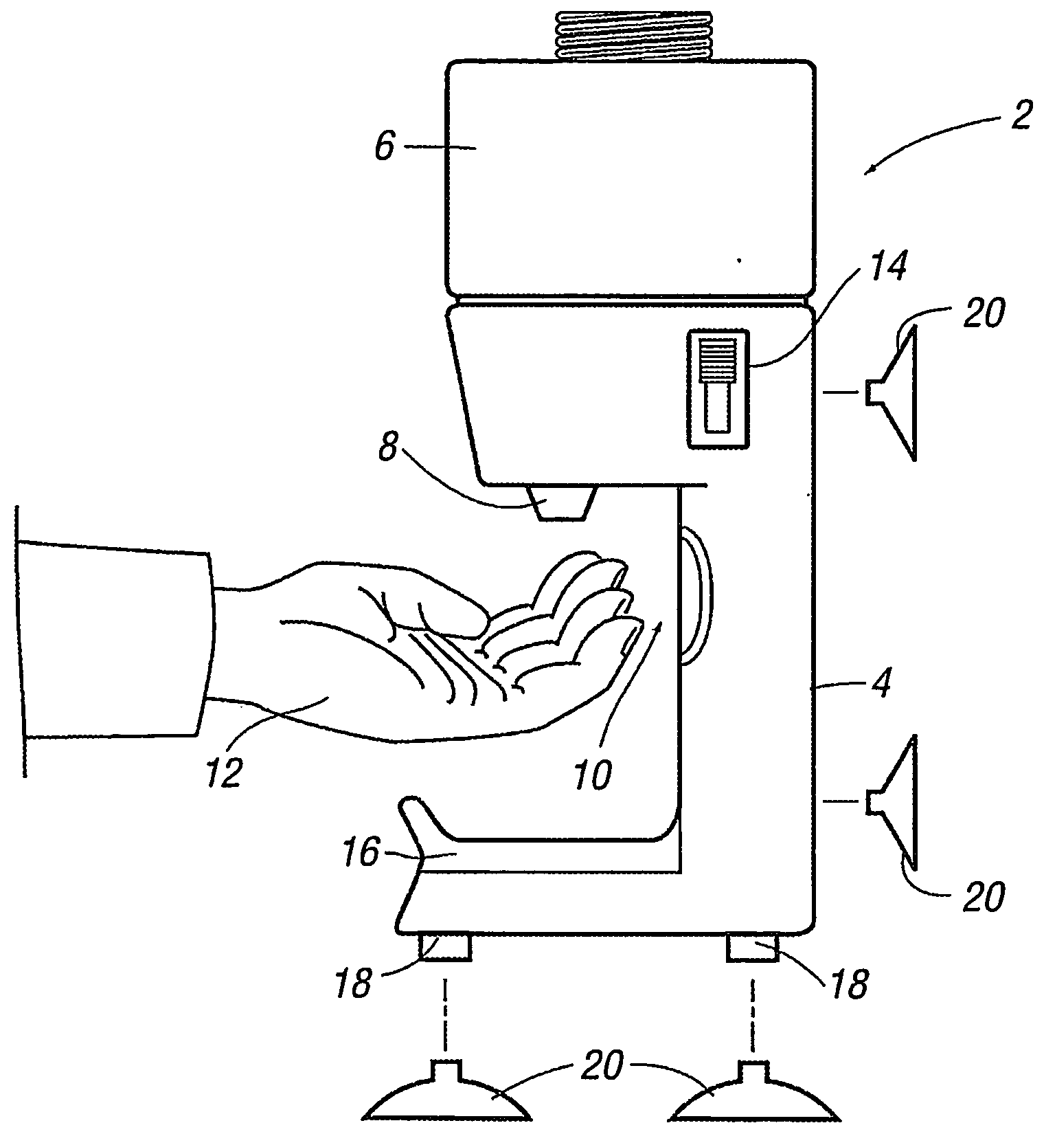
[0017]By providing the power source in the base or at least below the dispensing means, so the same can be removed from the liquid reservoir to a sufficient extent that any liquid which is emitted from the reservoir cannot contact the power source. This therefore means that the conventional need for sealing means for the power source housing and / or reservoir opening is reduced or removed and therefore reduces the cost of the product, allows the product to be reduced in size and / or for the liquid reservoir capacity to be increased and / or for access to be gained to the reservoir more easily.
[0018]It also, importantly, allows the function of the dispensing apparatus to be more reliable as the risk of failure of the power source or the power source connections due to the liquid ingress is reduced.
[0020]In one embodiment, the apparatus includes dispensing adjustment means which allow the user to select the quantity of the liquid which is dispensed on each occasion. For example, if the apparatus is to be used by a child, he / she will require less liquid than an adult and the apparatus can be adjusted according.
[0022]In one embodiment, control means are provided for the dispensing means which ensure that a quantity of liquid is dispensed for a predetermined period of time or, alternatively, a particular volume of liquid is dispensed. Typically, once the sensor has been activated by the detection of a person's anatomy and a portion of liquid dispensed, a time interval is required to elapse before a further quantity of liquid will be dispensed. This is to prevent the possibility of, for example, a child keeping his / her hands in the vicinity of the sensor even after a portion of the liquid has been dispensed and thereby causing, in quick succession, a series of dispensations of liquid which is not required.
[0029]In one embodiment, in addition to causing the activation of the dispensing means, the operation of the sensor, when it detects the presence of a hand or the like, causes the operation of visual and / or audible means provided as part of the apparatus, thereby adding to the attractiveness of the application.

Problems solved by technology

This form of dispenser requires physical manipulation by a user and can be time consuming and / or difficult for certain persons, such as the young or elderly, to perform the manual manipulation.
In either case, the apparatus, because the same is required to be used by large numbers of the public and may not be used in a careful manner, has to be designed to a completely different standard to that which would be provided for domestic use and, therefore, the size, expense and general design is impractical for use in domestic purposes.
This therefore means that in normal use and / or when refilling the reservoir there is a problem of ingression of liquid from the reservoir into contact with the power source.
This can damage the power sources and / or connections and hence cause the failure of the product.
However, the sealed lids can be difficult to open to refill of the reservoir, especially by children or the infirm, and the size of the sealed lids and housings mean that the overall size of the product is increased and / or the possible size of the liquid reservoir capacity is reduced, as well as increasing the expense of the product.
This increase in expense can make the seam commercially unfeasible for domestic use.
A problem which is experienced in domestic premises and, in particular, by parents at bath time for young children, is when they are attempting to bath the child who may not want to be bathed and who may prove to be particularly difficult.

Method used


Image

  • Dispensing  Apparatus
  • Dispensing  Apparatus
  • Dispensing  Apparatus

Examples


Embodiment Construction

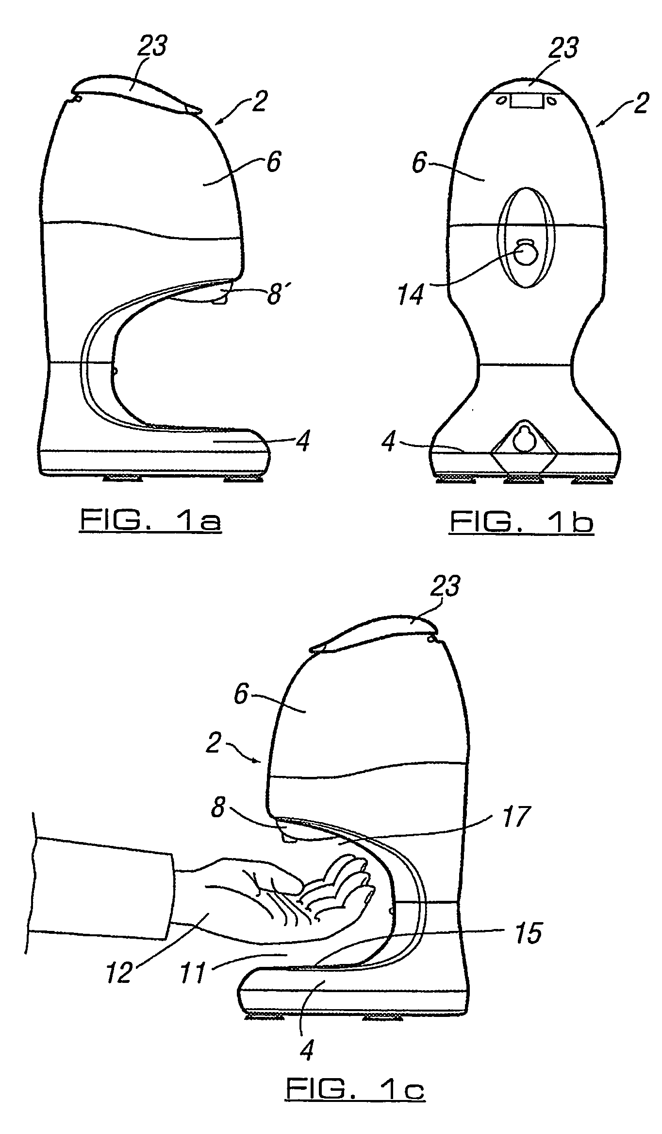
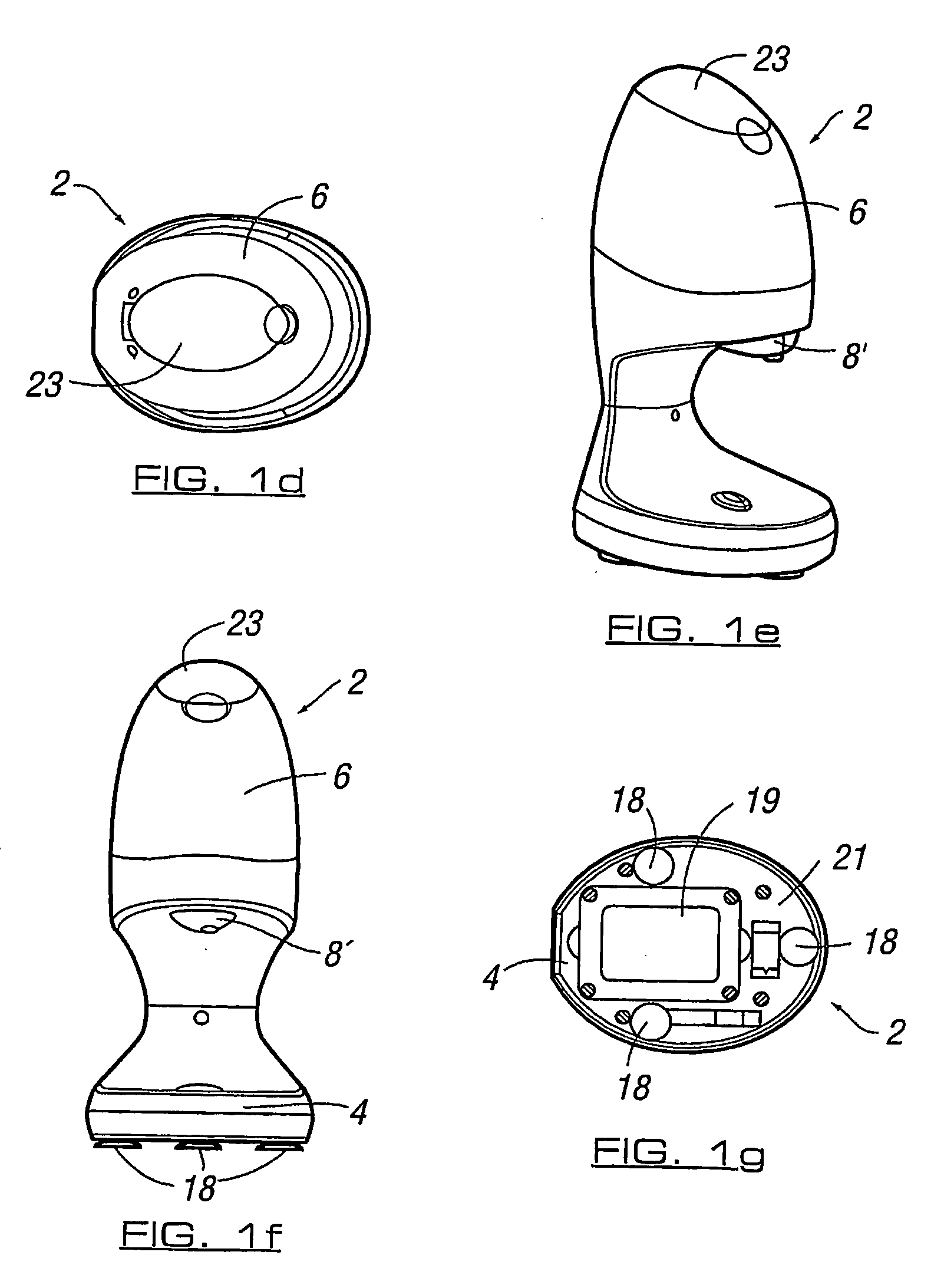
[0042]Referring first to FIGS. 1a-g, there is illustrated apparatus 2 in accordance with one embodiment of the invention. The apparatus is herein described with reference to the dispensation of liquid soap, although it should be appreciated that any substance which is suitably fluid can be dispensed, such as toothpaste, gel or the like. While it is envisaged that the apparatus is of particular benefit to use in bathrooms, it is possible that other uses of the apparatus in other areas are possible and, therefore, the description herein provided should not be interpreted as limiting the potential use of the apparatus or the scope of protection afforded therefore.

[0043]In the example shown in FIGS. 1a-g, apparatus 2 includes a base unit 4, the underside of which is shown in FIG. 1g. The base unit 4 is connected to mount a reservoir 6 which holds the liquid to be dispensed. A dispensing means 8 including a motor or pump (not shown) and a dispensing outlet 8′ leading from reservoir 6 are...


PUM


Abstract

This invention provides a liquid dispensing apparatus such as, for example, a liquid soap dispensing apparatus. The apparatus can be provided as a self-contained unit including a reservoir provided at a spaced location from a base. Sensor means are provided to allow the selective dispensation of liquid from the reservoir upon the detection of a part of a user's anatomy in a position between the liquid reservoir and the base. A motor can be connected to an outlet from the liquid reservoir which allows a portion of the liquid to be dispensed in a controlled manner, and the power source for the motor is typically a battery or batteries and the same are located in the base. The provision of the batteries in the base, a position remote from the liquid reservoir, protects the batteries from the liquid and means that the liquid reservoir need not be provided with a sealing cap to prevent liquid from entering the power source and damaging the same.

Description

CROSS-REFERENCES TO RELATED APPLICATIONS[0001]This application is the United States National Phase of PCT Application No. PCT / GB2006 / 001108 filed 28 Mar. 2006 which claims priority to British Application No. 0512258.5 filed 16 Jun. 2005.STATEMENT REGARDING FEDERALLY SPONSORED RESEARCH OR DEVELOPMENT[0002]Not ApplicableTHE NAMES OF THE PARTIES TO A JOINT RESEARCH AGREEMENT[0003]Not ApplicableINCORPORATION-BY-REFERENCE OF MATERIAL SUBMITTED ON A COMPACT DISC[0004]Not ApplicableBACKGROUND OF THE INVENTION[0005]The invention to which this application relates is apparatus to allow for the dispensation, selectively, of a liquid such as, but not necessarily exclusively, a liquid gel or soap for use in cleaning hands or other parts of the anatomy.[0006]The provision of apparatus which allows for the dispensing of liquid gel (hereinafter referred to as liquid soap in a non-limiting manner) from containers is well known. The conventional apparatus typically takes two forms.[0007]The first is ...

Claims


Application Information

Patent Timeline
Patent Type & Authority Applications(United States)
IPC IPC(8): B67D5/08B67D5/22B67D5/00B05B11/00G01F11/00B67D7/08A47K5/12B67D7/22B67D99/00
CPCA47K5/1217
Inventor SCORGIE, IAIN
Owner MINDSINSYNC
Learn More