
Specimen grip, having a grip shell, for use in a materials testing machine

a technology of specimen grip and grip shell, which is applied in the direction of mechanical measuring arrangement, instruments, and mechanical means, can solve the problems of not being realistic through use of just conventional specimen grip assemblies, and achieve the effects of accurate simulation, light weight and elimination of any noticeable complian

Active Publication Date: 2009-06-04
DYNAMIC SYST INC
View PDF14 Cites 17 Cited by
  • Summary
  • Abstract
  • Description
  • Claims
  • Application Information

AI Technical Summary

Benefits of technology

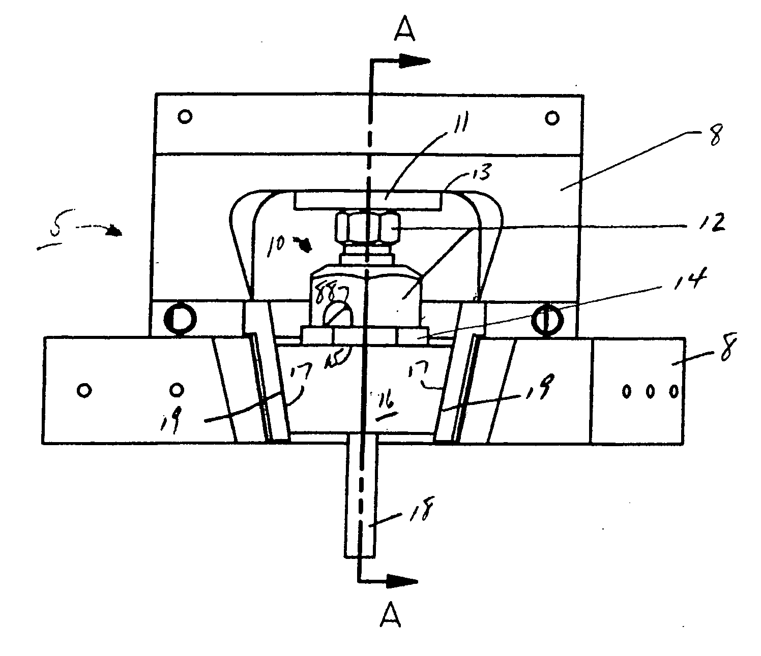
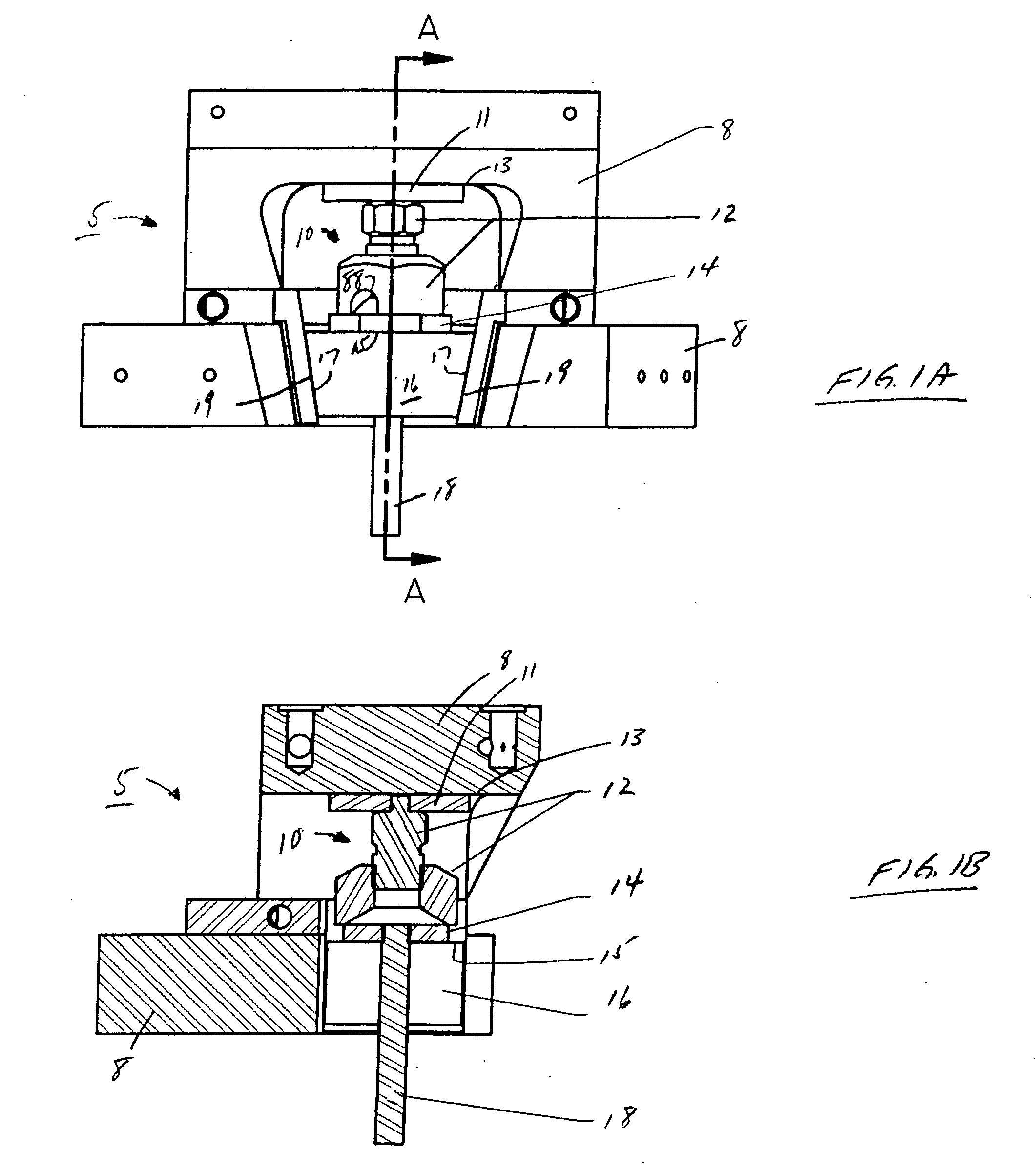
[0015]Interposition of the shell, i.e., positioned around the specimen grips and between the jaw housing and the grips, substantially, if not totally, eliminates any noticeable compliance from occurring in the specimen grips yet allows the resulting jaw assembly to be relatively light in weight. This, in turn, permits the jaw assembly to be used in a test stand to accurately simulate certain high-speed metal forming operations that require high stroke rates which, given the compliance in the specimen grips that would otherwise result in the absence of using the shell, would not be realistic through use of just conventional specimen grip assemblies. Consequently, use of the inventive specimen grip assembly would likely and advantageously extend the utility of a materials testing system that were to employ it.

Problems solved by technology

This, in turn, permits the jaw assembly to be used in a test stand to accurately simulate certain high-speed metal forming operations that require high stroke rates which, given the compliance in the specimen grips that would otherwise result in the absence of using the shell, would not be realistic through use of just conventional specimen grip assemblies.

Method used


Image

  • Specimen grip, having a grip shell, for use in a materials testing machine
  • Specimen grip, having a grip shell, for use in a materials testing machine
  • Specimen grip, having a grip shell, for use in a materials testing machine

Examples


first embodiment

[0040]With the above in mind, FIG. 4 depicts a top perspective view of unitary grip shell 400 as used in the present invention and FIG. 5 depicts a cross-sectional view of grip shell 400 taken along lines 5-5 shown in FIG. 4. For enhanced understanding, the reader should simultaneously refer to these two figures throughout the following discussion of grip shell 400.

[0041]Grip shell 400 is a unitary piece of material typically formed from steel, stainless steel or other sufficiently strong material depending on physical requirements of the test stand and peak forces that are likely to occur during each “hit”. For use in conjunction with the present assignee's GLEEBLE dynamic thermo-mechanical materials testing systems, grip shell 400 is preferably formed of 17-4 PH stainless steel. This material, being a martensitic, precipitation-hardened stainless steel, provides a good combination of strength, toughness and corrosion resistance.

[0042]As shown, grip shell 400 has a truncated, frust...

second embodiment

[0043]Alternatively, FIG. 6 depicts the inventive specimen grip assembly, here being assembly 600, that is particularly suited for use in thermo-mechanical materials testing systems, such as the GLEEBLE systems, that employ self-resistive specimen heating, i.e., where heating current serially flows through the specimen itself. FIG. 7 depicts an exploded view of inventive grip assembly 600 shown in FIG. 6, and in the same perspective view as in the latter figure, and illustrating various components that constitute inventive grip assembly 600; FIG. 8 depicts a cross-sectional view of inventive specimen grip assembly 600 taken along lines 8-8 shown in FIG. 6. For enhanced understanding, the reader should simultaneously refer to these three figures throughout the ensuing discussion.

[0044]Grip assembly 600 contains grip shell 610, inner inserts 635A and 635B, and outer inserts 633A and 633B. Similar to grip shell 400, grip shell 610 is also preferably formed of 17-4 PH stainless steel. W...


PUM

PropertyMeasurementUnit
tensileaaaaaaaaaa
compressive forceaaaaaaaaaa
shapeaaaaaaaaaa

Abstract

A specimen grip assembly which can be used with a relatively light-weight jaw in a materials testing system. The specimen grip assembly illustratively contains a grip shell and a pair of wedge-shaped specimen grips. The shell has a truncated, frusto-pyramidal exterior shape with two outwardly facing inclined surfaces, both inclined at an angle and which matingly abut and slide against complementary inclined interior surfaces of the jaw. The grips are oriented in a recess within the shell such that inclined surfaces of the grips abut against interior complementary surfaces of the shell. The shell, containing the grips and specimen, is suitably positioned within the jaw, with the shell and grips then jacked into a fixed position. The shell substantially eliminates any noticeable compliance from the specimen grips that might otherwise arise from tensile and / or compressive forces applied to the jaw and specimen grip assemblies during a test program.

Description

CLAIM TO PRIORITY[0001]This application claims priority of my co-pending U.S. provisional patent application entitled “Specimen Grip, having a Grip Shell, for use in a Materials Testing Machine”, filed on Nov. 30, 2007 and assigned Ser. No. 61 / 005,058; and which is incorporated by reference herein.BACKGROUND OF THE DISCLOSURE 1. Field of the Invention[0002]The invention relates to apparatus for a specimen grip assembly which securely holds a test specimen in a jaw assembly of a materials testing machine. The present invention is well suited for use in a variety of different mechanical and thermo-mechanical materials testing machines, including those which provide compressive and tensile testing of a mechanical test specimen.[0003]2. Description of the Prior Art[0004]Conventional materials testing machines hold an end of a test specimen in proper position in a jaw during a mechanical test through any one of various mechanisms, including specimen grips, collets, or fixtures.[0005]In s...

Claims


Application Information

Patent Timeline
Patent Type & Authority Applications(United States)
IPC IPC(8): G01N3/02
CPCG01N2203/04G01N3/04
Inventor LINDEMAN, NORMAN A.
Owner DYNAMIC SYST INC
Learn More