Suspension control arm assembly for vehicles

a technology for suspension systems and control arms, which is applied in the direction of resilient suspensions, interconnection systems, vehicle components, etc., can solve the problems of affecting the stability of the vehicle, the link geometry of the typical beam rear axle is compromised, and the geometry tends to interfere with the traditional vehicle frame structure, so as to eliminate undesired compliance, reduce the effect of lateral and yaw stiffness, and eliminate the effect of undesired complian

Inactive Publication Date: 2007-03-01
GM GLOBAL TECH OPERATIONS LLC
View PDF37 Cites 5 Cited by
  • Summary
  • Abstract
  • Description
  • Claims
  • Application Information

AI Technical Summary

Benefits of technology

[0009] One advantage of the present invention is that a new control arm assembly is provided for a suspension system of a vehicle. Another advantage of the present invention is that the control arm assembly is provided for a beam axle suspension system of a vehicle. Yet another advantage of the present invention is that the control arm assembly has deflection characteristics that are tunable. Still another advantage of the present invention is that the control arm assembly eliminates undesired compliance. A further advantage of the present invention is that control arm assembly decouples fore / aft, lateral, and yaw compliances. Yet a further advantage of the present invention is that the control arm assembly incorporates a tri-bushing A-Arm lower link having geometry that increases the lateral and yaw stiffness without compromising the desired geometric steer and fore / aft compliance to achieve ride, handling, and noise and vibration performance. Still a further advantage of the present invention is that the control arm assembly provides less coupling of compliance modes, and thus less compromise in desired compliances that results in better vehicle handling, ride, and noise and vibration performance.
[0010] Other features and advantages of the present invention will be readily appreciated, as the same becomes better understood, after reading the subsequent description taken in conjunction with the accompanying drawings.

Problems solved by technology

Any yaw of the beam axle while driving over a road disturbance, steers the rear wheels, and correspondingly causes the vehicle to change the direction of its path.
The link geometry of a typical beam rear axle is compromised by physical interference of the links to other components and systems of the vehicle.
However, this link geometry tends to interfere with traditional vehicle frame structure.
However, this results in the beam axle having very low yaw stiffness, which causes steer effects of the beam axle when the wheel travels over road disturbances due to the fore / aft loading of the wheels.
Previous beam axle implementations have compromised beam yaw stiffness, lateral force stiffness, and fore / aft stiffness.
The compliances are highly coupled, and modifying one stiffness mode for a desired vehicle performance characteristic alters one of the other compliance modes in an undesirable manner.

Method used


Image

  • Suspension control arm assembly for vehicles
  • Suspension control arm assembly for vehicles
  • Suspension control arm assembly for vehicles

Examples


Embodiment Construction

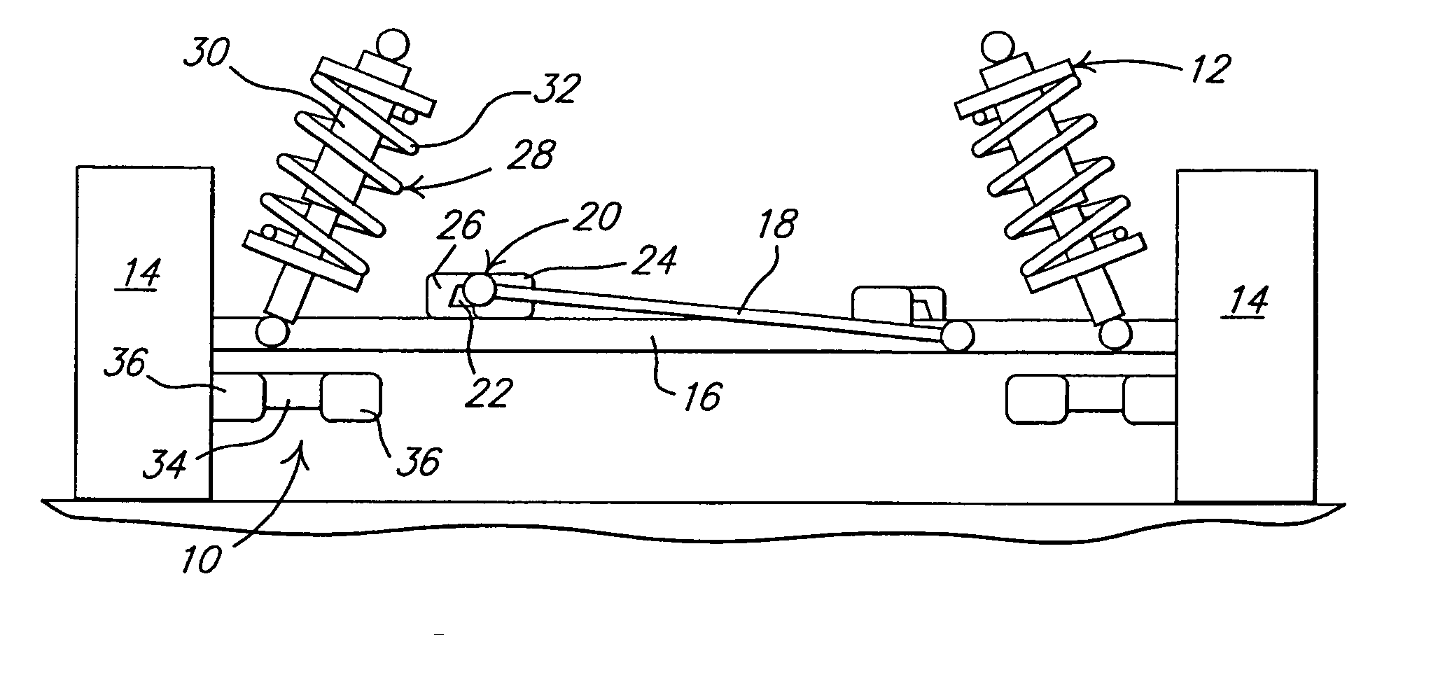
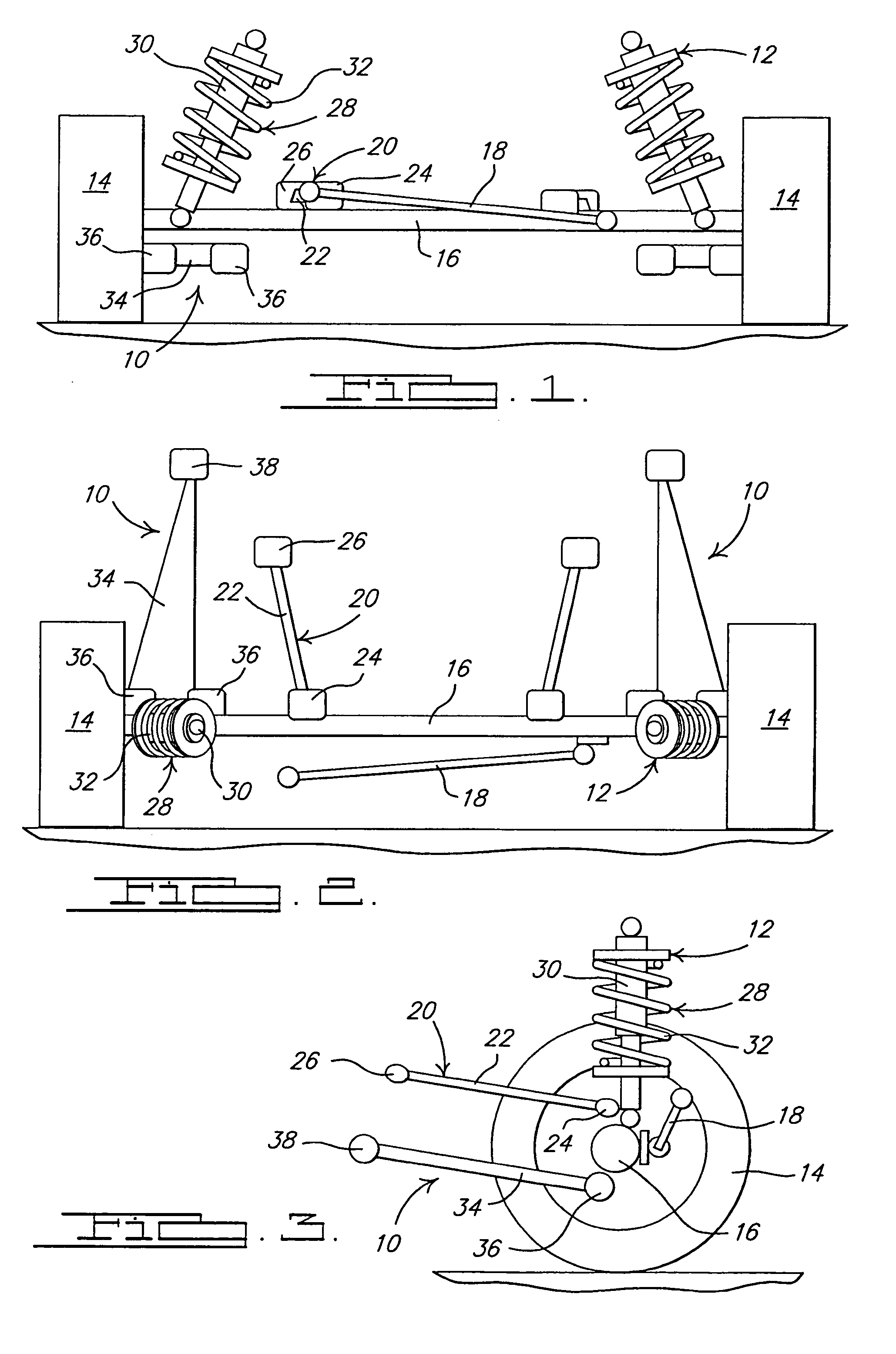
[0018] Referring to the drawings and in particular FIGS. 1 through 3, one embodiment of a control arm assembly 10, according to the present invention, is shown for a suspension system, generally indicated at 12, of a vehicle, such as a motor or automotive vehicle (not shown). The vehicle includes a frame (not shown), at least one, preferably a plurality of wheels 14, and a beam axle 16 extending laterally between a pair of the wheels 14. The beam axle 16 is generally circular in cross-sectional shape, but may have any suitable shape. It should be appreciated that the suspension system 12 is a beam axle suspension system that suspends the frame relative to the wheels 14, and could be of a driven or non-driven application.

[0019] The suspension system 12 includes a track bar 18 to locate the beam axle 16 in a cross car or vehicle orientation. The track bar 18 extends laterally and has one end connected to the beam axle 16 and another end connected to vehicle structure (not shown). The...


PUM


Abstract

A control arm assembly for a suspension system of a vehicle includes a control arm having a triangular shape for connection to vehicle structure and a beam axle of the vehicle. The control arm assembly also includes a plurality of bushings connected to the control arm and for connection to the vehicle structure and the beam axle of the vehicle.

Description

TECHNICAL FIELD [0001] The present invention relates generally to suspension systems for vehicles and, more particularly, to a control arm assembly for a suspension system of a vehicle. BACKGROUND OF THE INVENTION [0002] It is known to provide a beam axle suspension system for a vehicle. In a vehicle such as an automotive vehicle, the beam axle suspension system may be a five-link beam axle arrangement between a frame and wheels or tires of the vehicle. The beam axle arrangement typically includes a beam axle, upper and lower links, a track bar, and a spring and damper unit. In this arrangement, the beam axle extends between a pair of wheels and is located cross car via the lateral track bar. The beam axle is located fore and aft via the upper and lower links. The upper and lower links also locate the beam axle torsionally. The vertical location of this beam axle is located via the spring and damper unit. Other suspension arrangements may have the spring and damper as separate units...

Claims


Application Information

Patent Timeline
Patent Type & Authority Applications(United States)
IPC IPC(8): B60G9/00B60G3/00
CPCB60G7/00B60G9/00B60G2200/314B60G2206/124B60G2200/341B60G2204/148B60G2200/34
Inventor LOPEZ, JOSE M.HALL, WALLACE T.
Owner GM GLOBAL TECH OPERATIONS LLC
Why Eureka
Try Eureka