
Dermatome with ultrasonic cutting blade

a dermatome and ultrasonic technology, applied in the field of dermatomes with ultrasonic cutting blades, can solve the problems of generating excessive mechanical noise, requiring significant physical effort and coordination to operate, and prior art dermatomes have undesirable limitations

Inactive Publication Date: 2009-05-28
DADSON MFG CORP
View PDF5 Cites 41 Cited by
  • Summary
  • Abstract
  • Description
  • Claims
  • Application Information

AI Technical Summary

Benefits of technology

[0008]A first aspect of the present invention concerns an ultrasonic dermatome broadly including a body, an ultrasonic frequency generator, a blade element, and a gauge bar. The body includes a handle. The ultrasonic frequency generator is mounted to the handle. The blade element presents proximal and distal ends. The blade element is drivingly attached to the frequency generator adjacent the proximal end and presents a cutting edge along the distal end, with the cutting edge being operable to cut a skin graft. The gauge bar is supported by the body and positioned adjacent the cutting edge to engage the skin. The gauge bar and cutting edge are spaced apart to present a graft opening through which the skin graft is operable to pass when cut. The blade element is supported by the body to define a distal cantilevered blade section that includes the cutting edge. The distal cantilevered blade section is spaced apart from the body to restrict the body from damping ultrasonic energy transmitted from the ultrasonic frequency generator to the cutting edge.
[0009]A second aspect of the present invention concerns an

Problems solved by technology

Prior art dermatomes have a number of undesirable limitations.
For example, conventional dermatomes require significant physical effort and coordination to operate and typically require more than one person to perform the procedure of cutting a skin graft.
Powered dermatomes are also notorious for generating an excessive amount of mechanical noise.
Furthermore, the mechanical drive of prior art powered dermatomes are prone to undesirable wear and failure after only 20-30 hours of continuous use.

Method used


Image

  • Dermatome with ultrasonic cutting blade
  • Dermatome with ultrasonic cutting blade
  • Dermatome with ultrasonic cutting blade

Examples


Embodiment Construction

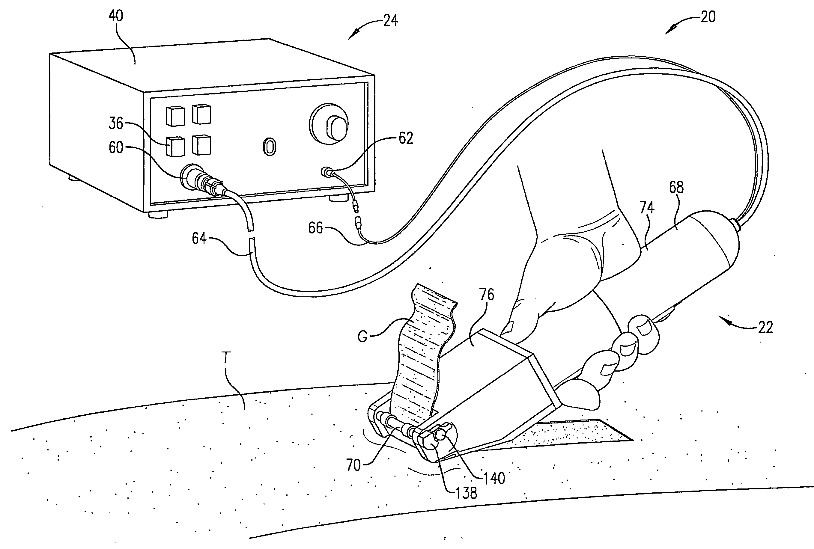
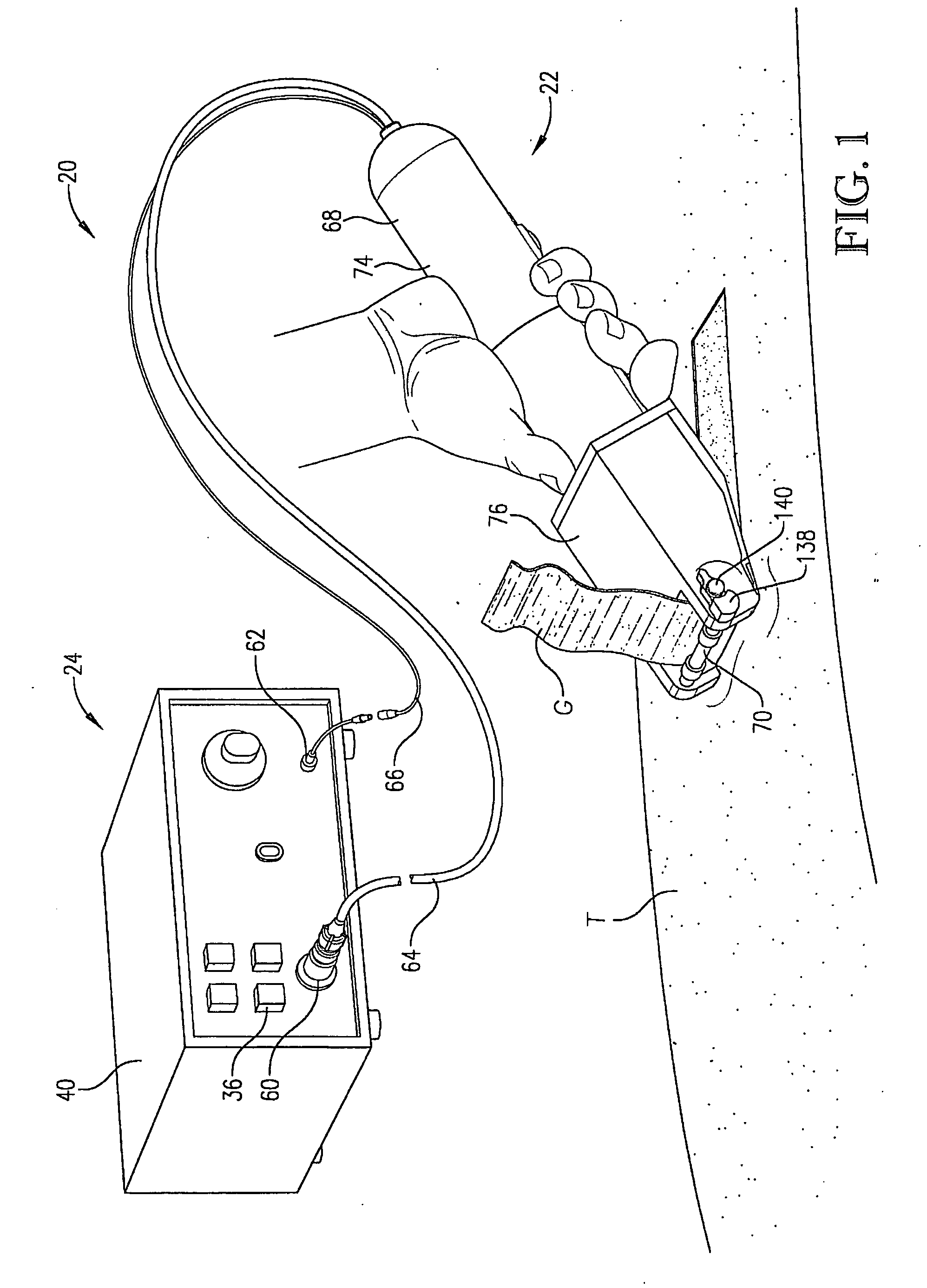
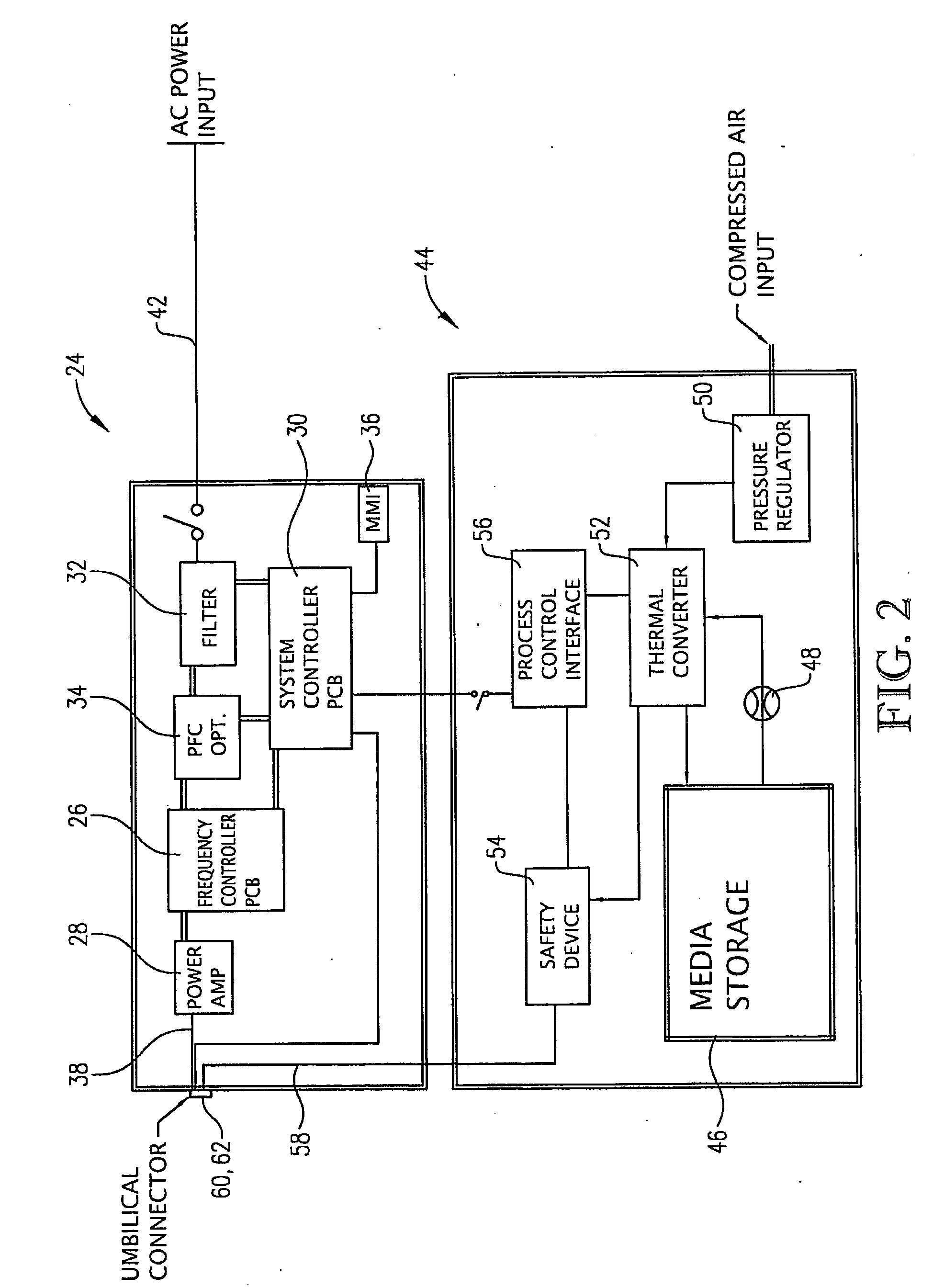
[0022]Turning initially to FIGS. 1 and 2, a dermatome assembly 20 is operable to remove a skin graft G from tissue T. The skin graft G removed by the dermatome assembly 20 is typically used in repairing an area of damaged skin, e.g., from burning, or for use in cosmetic surgery. The skin graft G may be harvested from tissue of a live patient or from a cadaver. The illustrated dermatome assembly 20 is particularly effective under extended use, e.g., for use at a skin bank where skin grafts can be harvested throughout the day. The dermatome assembly broadly includes an ultrasonic dermatome 22 and a power supply 24.

[0023]As will be discussed in greater detail, the power supply 24 drives the ultrasonic dermatome 22 and provides a supply of coolant. The power supply 24 broadly includes a frequency controller 26, a power amplifier 28, a system controller 30, a power filter 32, power factor correction 34, a power supply interface 36, a power output line 38, and a power supply housing 40. T...


PUM


Abstract

A dermatome assembly is operable to harvest a skin graft and includes an ultrasonic dermatome and a power supply. The ultrasonic dermatome includes a body and an ultrasonic blade assembly mounted in the body. The blade assembly includes a frequency generator and a cutting horn powered by the frequency generator. The cutting horn is spaced apart from the body so that the body is restricted from damping vibrational movement of the cutting horn. The dermatome assembly is operable to precisely control the thickness of the cut skin graft and also restrict the cutting horn from overheating.

Description

RELATED APPLICATION[0001]This application claims the benefit of U.S. Provisional Application No. 60 / 990,867, filed Nov. 28, 2007, entitled DERMATOME WITH ULTRASONIC CUTTING BLADE, which is hereby incorporated in its entirety by reference herein.BACKGROUND[0002]1. Field[0003]The present invention relates generally to devices for harvesting skin grafts. More specifically, embodiments of the present invention concern an ultrasonic dermatome.[0004]2. Discussion of Prior Art[0005]A dermatome is a medical instrument for cutting skin grafts and has been in use since the early 1900s. Prior art dermatomes include a blade with a straight razor-like edge and a head that can be adjusted to vary the width and thickness of the skin graft. Conventional dermatomes are either manually operated or electrically powered. Powered dermatomes are generally able to cut skin grafts more easily and more precisely than manual dermatomes. One electrically powered dermatome includes a blade that is driven in a ...

Claims


Application Information

Patent Timeline
IPC IPC(8): A61B17/322
CPCA61B17/322A61B17/320068A61B2017/320071A61B2017/320089
Inventor LUCAS, JAMES RAYMONDJONES, MARK LOYDALDRICH, JAMES EARLLUCAS, PETER BARRETTRUSS, NORBERTCOWDEN, SHANE E.
Owner DADSON MFG CORP
Learn More