
Method And Apparatus Using A Split Case Die To Press A Part And The Part Produced Therefrom

a split-case die and press technology, applied in the field of metallurgical processes, can solve the problems of limited green part shape and damage to parts

Inactive Publication Date: 2009-05-28
KENNAMETAL INC
View PDF38 Cites 40 Cited by
  • Summary
  • Abstract
  • Description
  • Claims
  • Application Information

AI Technical Summary

Benefits of technology

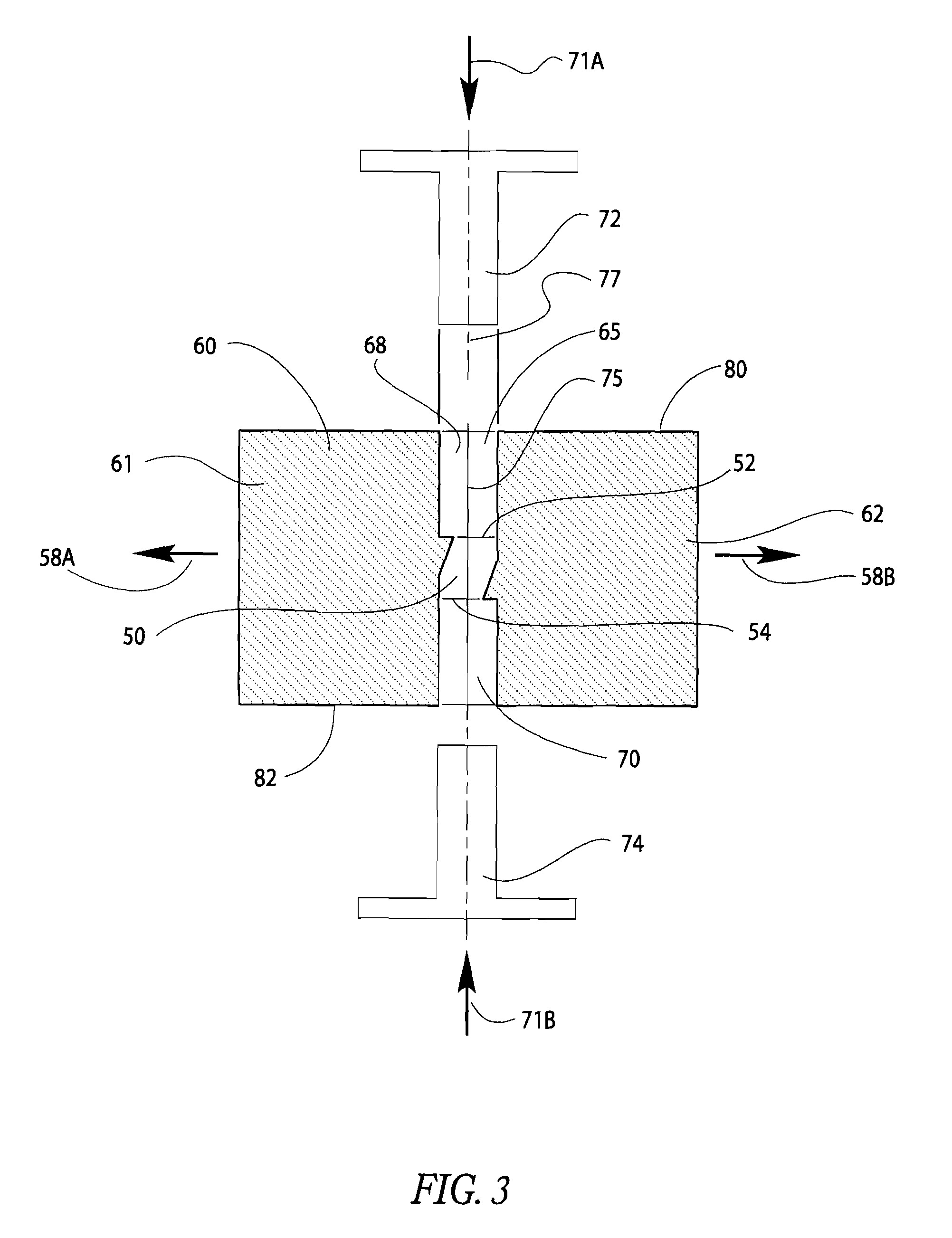
[0009]In another embodiment, a die for use with a uni-axial press for forming a compressed part from powder has top and bottom outer surfaces and a cavity extending therethrough along a pressing axis. The cavity is made up of a die chamber having walls with ends defining the shape of the part in the compressed state. The die is comprised of at least two separable die parts, wherein each die part is adapted to move only in a direction other than parallel to the pressing axis. Each die part has a chamber segment which, together with the other chamber segment(s), define the die chamber and parting line surfaces within the chamber segment which, in the assembled die, contact adjacent parting line surfaces within the chamber segment of the one or more other die parts to surround and define the die chamber. The chamber wall has at least one portion that forms a positive angle with the pressing axis and at least one other portion that forms a negative angle with the pressing axis.

Problems solved by technology

The green part is ejected through the unified die cavity and, as a result, the shape of the green part is limited to a shape able to “slide” through and out of the die cavity.
Not only does this requirement dictate limitations on the shape of the green part but, furthermore, the die parts sliding over the green part introduce friction against the part that might damage the part.

Method used


Image

  • Method And Apparatus Using A Split Case Die To Press A Part And The Part Produced Therefrom
  • Method And Apparatus Using A Split Case Die To Press A Part And The Part Produced Therefrom
  • Method And Apparatus Using A Split Case Die To Press A Part And The Part Produced Therefrom

Examples


Embodiment Construction

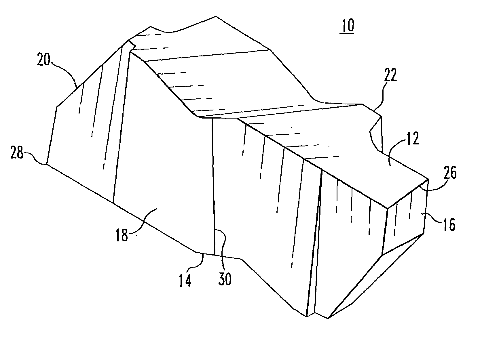
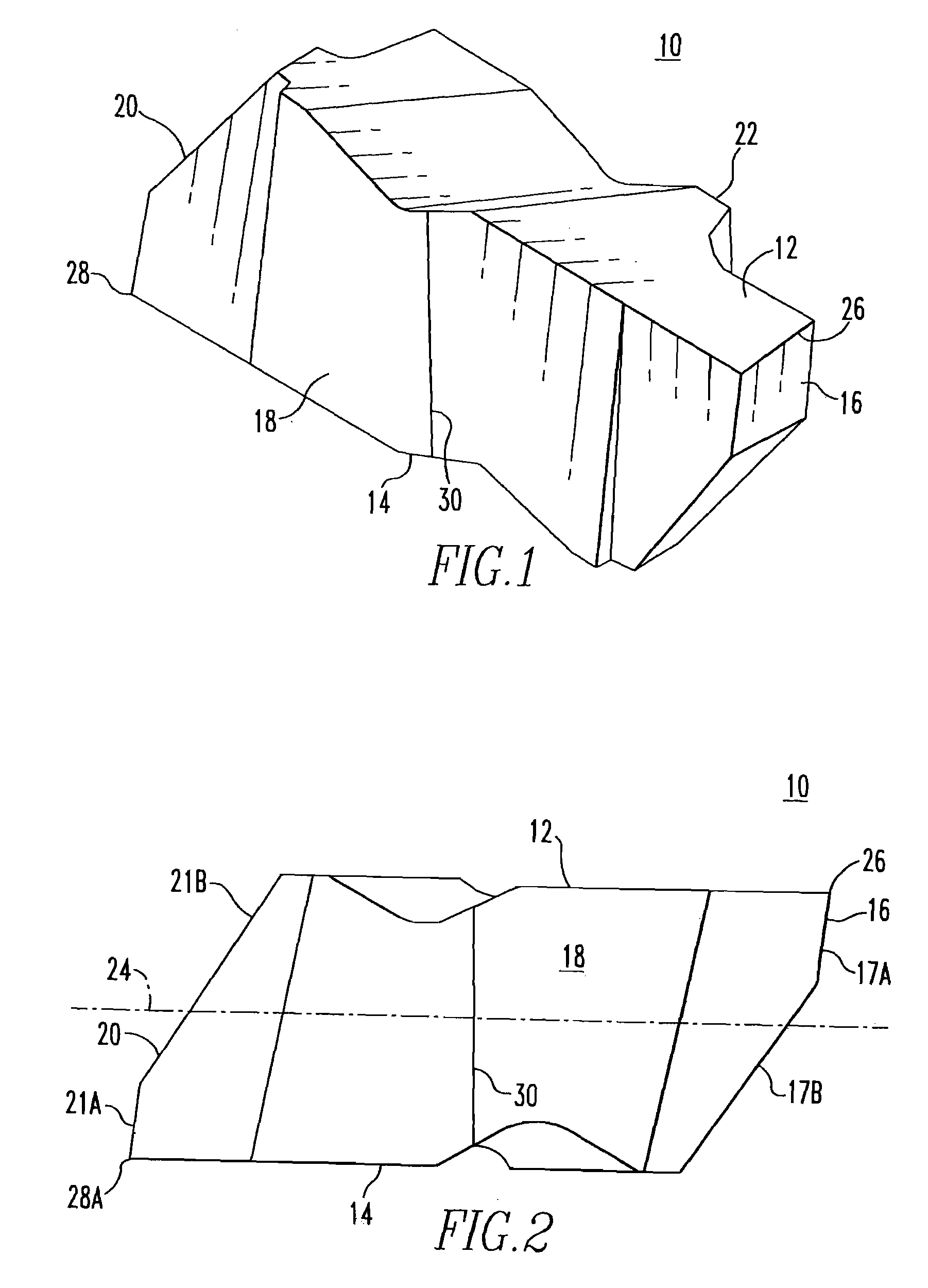
[0035]FIGS. 1 and 2 illustrate a green part 10 that, after sintering, will be a cutting insert. However, this green part 10 will be discussed as it applies to a split case die. FIG. 3 illustrates an arrangement showing a die 60 having the die chamber 50 with a shape generally similar to that of the side view of green part 10 illustrated in FIG. 2. In particular, the green part 10 has a top surface 12 and a bottom surface 14 with side walls 16, 18, 20 and 22 therebetween. Sidewall 16 has a generally vertical segment 17A extending from the top surface 12 and an angled segment 17B extending to the bottom surface 14. Additionally, sidewall 20 has a generally vertical segment 21A extending from the bottom surface 14 and an angled segment 21B extending to the top surface 12. The green part 10 is symmetric about a centerline 24. It should be noted that the angled segments 17B, 21B of the side walls 16, 20 both overlap the centerline 24. The green part 10 has an edge 26 and a diametrically ...


PUM

PropertyMeasurementUnit
cone angleaaaaaaaaaa

Abstract

A split case die is used to press powder, wherein the die parts are moveable in a direction non-parallel to the direction of the pressing axis. The part produced by such a split case die has an external surface with parting line marks oriented in a direction non-perpendicular to the pressing axis.

Description

BACKGROUND OF THE INVENTION[0001]1. Field of the Invention[0002]The invention is directed to a metallurgical process for the consolidation of powder, wherein the process involves the utilization of a split case die. The subject invention is also directed to a part produced from such a process.[0003]2. Description of Related Art[0004]Fabrication of cutting inserts from sinterable powder, i.e. metallurgical cermets or ceramic powders, involves compaction of the sinterable powder with or without a fugitive binder into a pre-sintered green part. Subsequent sintering of the green part produces a finished part which may be a cutting tool. Compaction takes place under high pressure obtained through large opposing forces generated by top and bottom rams urged into a die cavity formed in a die containing the sinterable powder.[0005]U.S. Pat. No. 6,986,866 is directed to a method and apparatus for cross-hole pressing to produce cutting inserts, whereby a solid unified die having a die cavity ...

Claims


Application Information

Patent Timeline
Patent Type & Authority Applications(United States)
IPC IPC(8): B22F3/03
CPCB22F3/03B22F2003/031Y10T428/12014B30B15/022Y10T428/24893B22F2003/033B30B11/007
Inventor GUBANICH, RICHARD J.DINCO, EDWARD M.MIZGALSKI, KENT P.
Owner KENNAMETAL INC
Learn More