
Method for routing and load balancing in communication networks

Active Publication Date: 2009-05-28
INTERDIGITAL CE PATENT HLDG
View PDF1 Cites 13 Cited by
  • Summary
  • Abstract
  • Description
  • Claims
  • Application Information

AI Technical Summary

Benefits of technology

[0022]Mesh routing as well as load balancing is performed in a joint fashion in the method according to the invention; and
[0023]The method according to the invention has a unique cross-layer approach in that it takes MAC and routing into account at the same time, which is unlike the prior art.
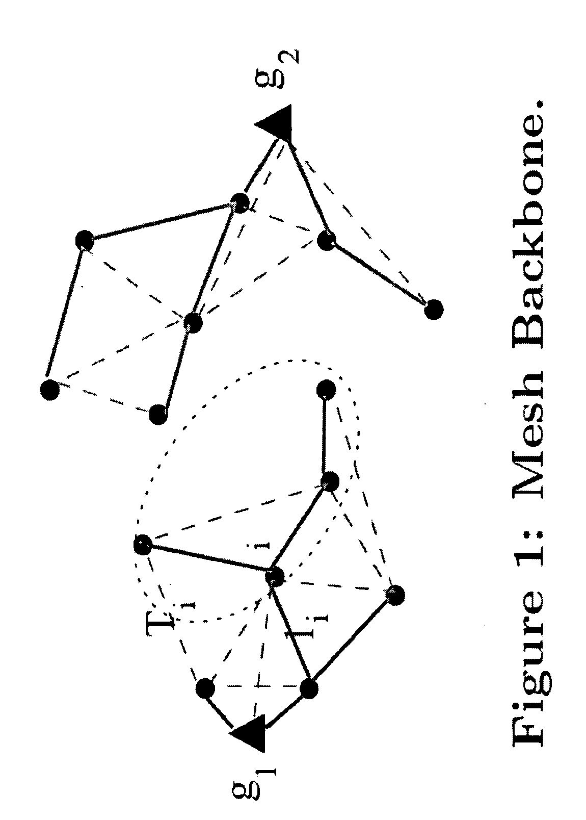
[0024]The present invention can be defined as a tractable, distributed, and greedy mesh routing method that jointly addresses the MAC interactions between the links as well as load balancing across the gateways. The solution according to the present invention works around the tractability problem arising from the interaction between MAC and routing, and jointly solves the problem of MAC-aware routing and load balancing. Instead of using shortest path routing, the solution according to the present invention determines a delay optimal routing forest (union of disjoint trees rooted at the gateways).
[0025]The invention allows to optimize resources for mesh routing and load balancing.
[0026]The method according to the invention is beneficial to the mesh network scenarios which have topology imbalance. Such imbalance often arises when one or more gateway nodes fail. Simulation results show that in scenarios of gateway failures, the solution according to the invention results in 30-60% throughput improvement over other load balancing techniques, as well as over other proposed routing solutions (see FIG. 4).
[0027]For scenarios in which there is no load imbalance, the solution according to the invention performs as well as, or marginally better than other proposed solutions.

Problems solved by technology

Furthermore, in a wireless network, the links have complex interdependence due to their MAC-layer interaction through the CSMA-CA (Carrier Sense Multiple Access with Collision Avoidance) protocol.

Method used


Image

  • Method for routing and load balancing in communication networks
  • Method for routing and load balancing in communication networks
  • Method for routing and load balancing in communication networks

Examples


Embodiment Construction

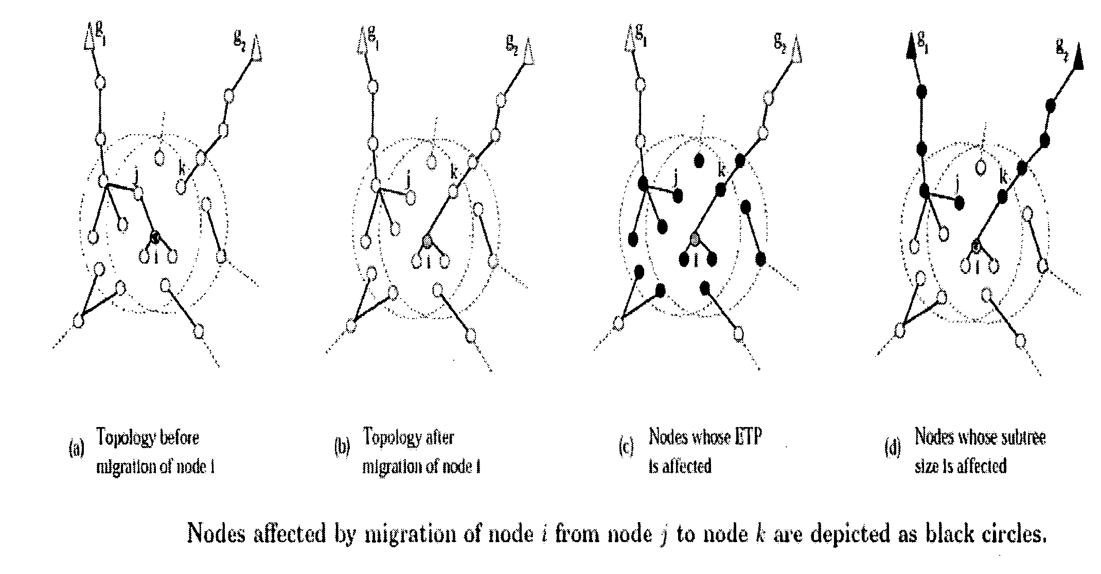
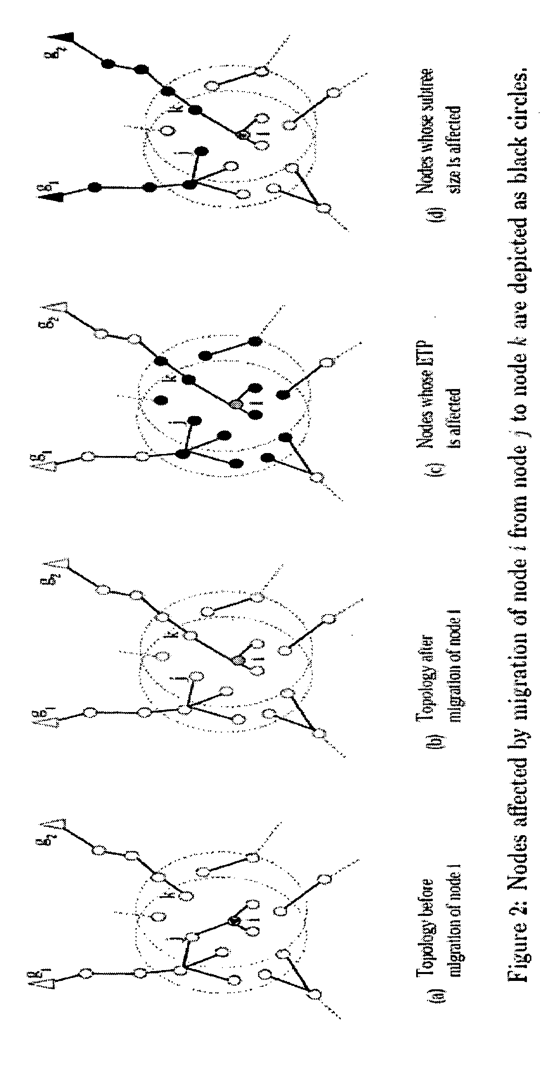
[0033]In the invention, a mesh network comprises a plurality of nodes.

[0034]The node 1 shown on FIG. 3 comprises a communication interface 11, a processor 12, a volatile memory 13 and a non-volatile memory 14.

[0035]Consider a mesh network in which G is the set of gateways that have direct connectivity to the Internet, and M is the set of mesh nodes. Each mesh node Iε M connects to a single gateway, G(i) ε G, using other mesh nodes. In this case, mesh node i is considered to be associated with gateway G(i). Nodes are organized in disjoint trees Tgi, each tree rooted at a gateway node gi, ε G. Let T be the union of all these trees. Thus, T corresponds to one possible choice of routing. The subtree rooted at mesh node i ε M is denoted by Ti. Note that Ti includes node i. All the nodes have a single radio for mesh communication, and operate over a common channel. The latter assumption is used because if a single radio is available for mesh communication, monitoring of link qualities ove...


PUM


Abstract

The invention concerns a method of configuring the topology of a communication network comprising a plurality of nodes (i, j, . . . , N), said communication network being organized as a forest structure comprising trees and subtrees, wherein at least one node i maintains a periodic timer and an expiration of said timer of said node i triggers the steps of:searching, by said node i, a parent node;selecting, by said node i, a parent node using at least throughput and subtree size as selection criteria ; andmigrating said node i to the selected parent node along with its subtree size.Preferably, said step of selecting a parent node by said node i comprises a sub-step of executing a function having as parameters respective subtree sizes of a node j before and after the migration of said node i to another node k.

Description

FIELD OF THE INVENTION[0001]The present invention pertains to the field of communication networks.[0002]The present invention more particularly relates to a method of configuring the topology of a communication network.BACKGROUND OF THE INVENTION[0003]Mesh networking can be defined as a way to route data, voice and instructions between nodes. It allows for continuous connections and reconfiguration around broken or blocked paths by “hopping” from node to node until the destination is reached. A mesh network whose nodes are all connected to each other is a fully connected network. Mesh networks differ from other networks in that the component parts can all connect to each other via multiple hops, and they generally are not mobile. Mesh networks can be seen as one type of ad hoc network.[0004]A node is a critical element of any computer network. It can be defined as a point in a network at which lines intersect or branch, a device attached to a network, or a terminal or other point in...

Claims


Application Information

Patent Timeline
IPC IPC(8): H04L12/28
CPCH04L45/02H04L45/124H04L45/48H04W40/34H04W40/246H04W40/248H04W40/04H04L45/488H04L12/28
Inventor MHATRE, VIVEKLUNDGREN, HENRIKDIOT, CHRISTOPHEBACCELLI, FRANCOIS
Owner INTERDIGITAL CE PATENT HLDG
Learn More