
Spur gear drive for an internal combustion engine

a gear drive and internal combustion engine technology, applied in the direction of valve drives, valve details, valve arrangements, etc., can solve the problems of large installation space and relatively complex production of double gears, and achieve the effect of being smaller and lighter

Inactive Publication Date: 2009-05-28
DAIMLER AG
View PDF0 Cites 11 Cited by
  • Summary
  • Abstract
  • Description
  • Claims
  • Application Information

AI Technical Summary

Benefits of technology

[0007]In a spur gear drive for driving the camshaft of an overhead valve internal combustion engine wherein the drive power is transmitted from the crankshaft to the camshaft via spur gears mounted on the crankshaft and the camshaft which is rotatably supported on the cylinder head, a third, intermediate, gear is adjustably supported in the power train between engine block-mounted gears and cylinder head-mounted gears so that changes in the distance between the crankshaft and the camshaft can be accommodated and, with the use of smaller gears, the spur gear drive becomes smaller and lighter overall.
[0008]According to a preferred embodiment of the invention, an oil pump for supplying the internal combustion engine with lubricant is arranged below the crankshaft axis as viewed in the direction of the latter, and therefore situated opposite the camshaft or camshafts with respect to the crankshaft axis. Accordingly, the spur gear according to this preferred embodiment is characterized in that an oil pump gear is arranged, with respect to the crankshaft axis, opposite the crankshaft gear. It is thereby possible for the spur gear drive to be of narrow design.

Problems solved by technology

Double gears are however relatively complex to produce, and additionally require a relatively large installation space.

Method used


Image

  • Spur gear drive for an internal combustion engine
  • Spur gear drive for an internal combustion engine
  • Spur gear drive for an internal combustion engine

Examples


first embodiment

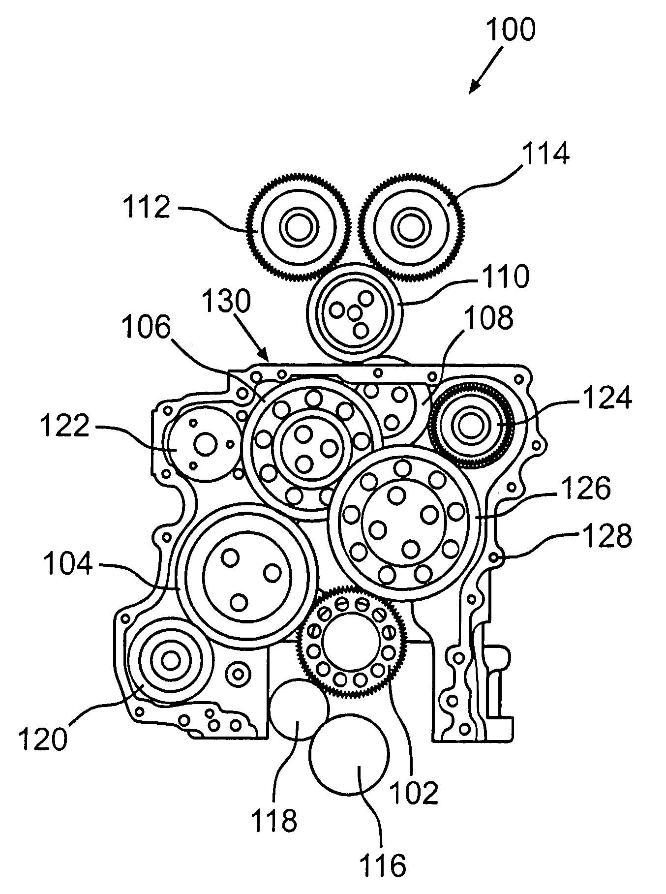
[0025]The preferred first embodiment of a spur gear drive 100 according to the invention as shown in FIG. 1 is provided for an internal combustion engine that is, specifically, a diesel engine with a 10.6 liter displacement volume. The spur gear drive 100 comprises a crankshaft gear 102 which drives a first camshaft gear 112 and a second camshaft gear 114 via a first intermediate gear 104, a second intermediate gear 106, a third intermediate gear 108 and a fourth intermediate gear 110. The first camshaft gear 112 serves for controlling the inlet valves, and the second camshaft gear 114 serves for controlling the outlet valves, so that, as it can be seen from FIG. 1, the internal combustion engine is a so-called DOHC machine.

[0026]The camshaft gears 112, 114 are arranged for driving a first and a second camshaft. The spur gear drive 100 extends below the crankshaft gear 102, and at the end opposite the camshaft gears 112, 114, is provided with an oil pump gear 116 which is driven by ...

second embodiment

[0038]In connection with FIG. 3 it is explained how a third intermediate gear 208 can be arranged so as to be moveable with respect to an upper edge 230 of an engine block or, respectively, a gear supported on the cylinder head of the engine, which is shown in particular for the spur gear drive 200 of the second embodiment shown in FIG. 2.

[0039]The third intermediate gear 208 is rotatably supported by a bearing journal 232 which is mounted to the cylinder block (not shown—FIG. 3 shows the gear arrangement from the rear, that is the cylinder block side) by mounting bolts 236. The bearing journal is held by a pin 234, which extends into a bore in the cylinder block front wall and is pivotally supported thereby. The bolts 236 extend through elongated holes 238 in the bearing journal 232 so that the bearing journal can be firmly mounted to the cylinder block front wall by tightening of the bolts 236. With the bolts 236 loosened the bearing journal 232 can be pivoted about the pin 234 du...


PUM


Abstract

In a spur gear drive for driving the camshaft of an overhead valve internal combustion engine wherein drive power is transmitted from the crankshaft to the camshaft via spur gears mounted on the crankshaft and the camshaft which is rotatably supported on the cylinder head, a third, intermediate, gear is adjustably supported in the power train between engine block-mounted gears and cylinder head-mounted gears so that changes in the distance between the crankshaft and the camshaft can be accommodated and, with the use of smaller gears, the spur gear drive becomes smaller and lighter overall.

Description

BACKGROUND OF THE INVENTION[0001]The invention relates to a spur gear drive for an internal combustion engine including a crankshaft gear and at least one camshaft gear with intermediate spur gears for transferring power from the crankshaft gear to the camshaft gear or gears.[0002]Spur gear drives of this type are known in practice for driving camshafts and engine auxiliary units. Such spur gear drives are used in particular in internal combustion engines with a large displacement volume as they are used for example in utility motor vehicles.[0003]A spur gear drive for an internal combustion engine is also known from DE 25 02 033 A1, wherein, a camshaft gear is driven by a crankshaft gear via intermediate spur gears.[0004]The gears of the spur gear drive transmit power and adapt the rotational speed to the requirements of the auxiliary units and of a first and, if applicable, a second camshaft. The transmission ratio between the crankshaft and camshafts of 1:0.5 required for a four-...

Claims


Application Information

Patent Timeline
Patent Type & Authority Applications(United States)
IPC IPC(8): F01L1/02
CPCF01L1/02F02B67/04F01L1/026
Inventor DUZZIE, THOMASEBERLE, FRANKGIEB, HARALDKENNEDY, LAWRENCE
Owner DAIMLER AG
Learn More