Eureka AIR delivers breakthrough ideas for toughest innovation challenges, trusted by R&D personnel around the world.

Heat convection dissipater for LED lamp

a technology of heat dissipation and led lamps, which is applied in the direction of indirect heat exchangers, semiconductor devices of light sources, lighting and heating apparatus, etc., can solve the problems of long time-consuming and laborious heating, low heat dissipation efficiency, and long time-consuming heating, so as to increase the heat dissipation effect of led lamps and prolong the life

Inactive Publication Date: 2009-05-21
CHEN SHYH MING
View PDF5 Cites 26 Cited by
  • Summary
  • Abstract
  • Description
  • Claims
  • Application Information

AI Technical Summary

Benefits of technology

[0008]Moreover, the present invention can increase the heat dissipating effect of an LED lamp which can be applied to a vehicle, as an outdoor lamp and has a longer lifetime.

Problems solved by technology

Generally, high power LED has a problem of heat dissipation.
Despite the way used for heat dissipating, the temperature at the second end will increase for a long time.
This is because above said heat dissipating ways can not provide a good efficiency.
However it is possible that the LED light is installed outdoors (such as a load light or a vehicle light) so that the fan will destroy as it is used for a long time.

Method used


Image

  • Heat convection dissipater for LED lamp
  • Heat convection dissipater for LED lamp
  • Heat convection dissipater for LED lamp

Examples


second embodiment

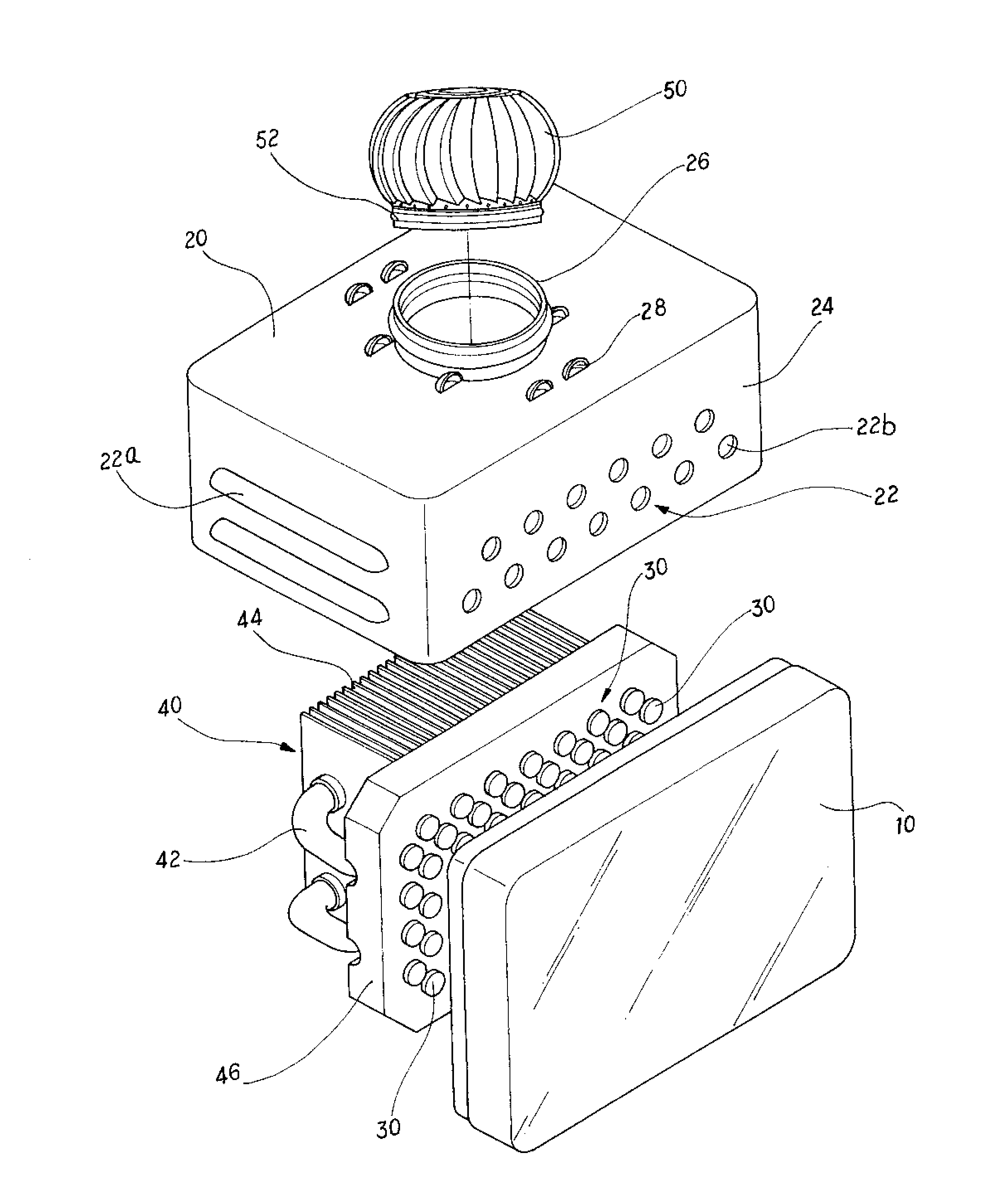
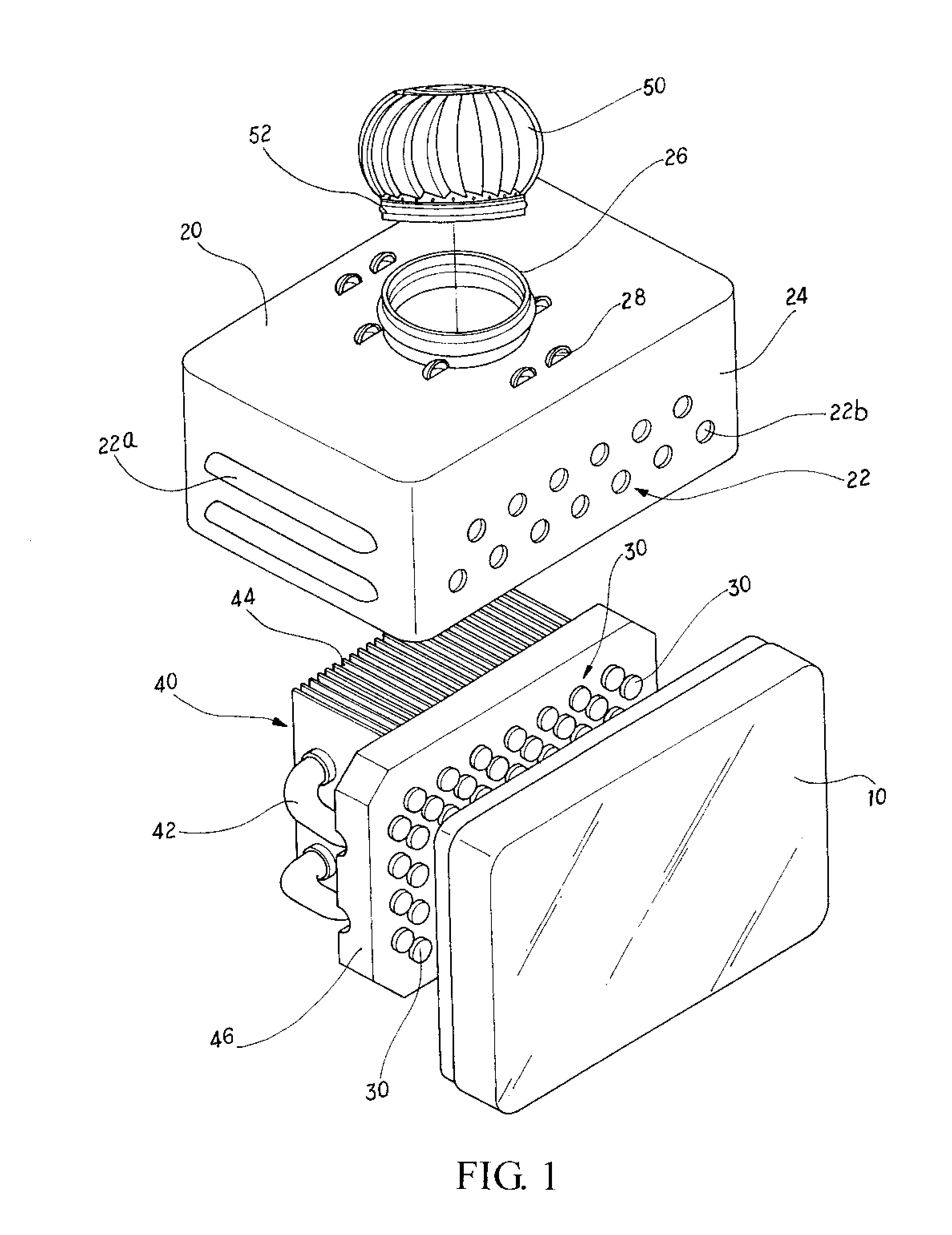
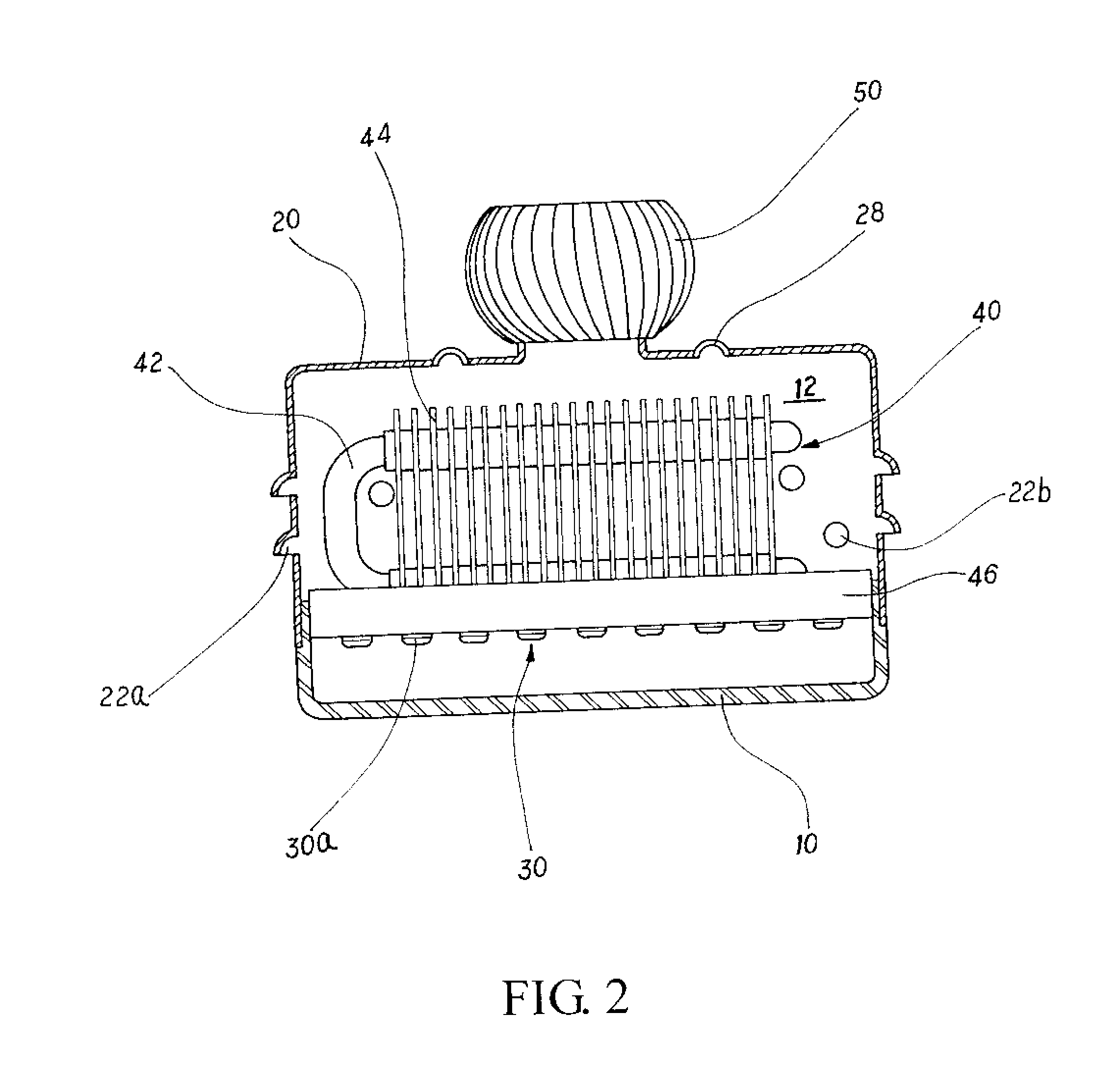
[0030]Referring to FIG. 4, the present invention is illustrated. For conforming various assembly environment, a flat deign is used in the present invention. In that, the air holes 22a, 22b are formed at the lateral side 24 of the housing 20. The blade wheel 50 is installed at the lateral side 24. The air holes 22 will guide cool air into the internal space 12 so as to cool the heat tube 42 and the heat dissipating sheets 44. Furthermore, the blade wheel 50 is driven to rotate. Thus air flows cyclically. In this embodiment, the height can be reduced by draining air laterally.

[0031]Referring to FIGS. 5 and 6, the third and fourth embodiment of the present invention is illustrated. In this embodiment, those identical to the above embodiment will not be further described herein. Only those different from above embodiment are described. The difference of the present invention from the first embodiment is that the shape of the housing 20. See FIG. 5, an upper side of the housing 20 about ...

fifth embodiment

[0032]Referring to FIG. 7, the present invention is illustrated. In this embodiment, those identical to the above embodiment will not be further described herein. Only those different from above embodiment are described. In this embodiment, a width of the housing 20 is greater than that of the optical mask 10. Level of the air holes 22 is approximately equal to that of the light emitting diode module 30. The external cool air will flow into the housing 20 so as to cool the heat tube 42 and the heat dissipating sheets 44 and to drive the blade wheel 50 to rotate. Air flows cyclically. However in this embodiment, the air holes 22 can be installed around the periphery of the optical mask 10.


PUM


Abstract

A heat convection dissipater for an LED lamp, comprises a convection heat dissipating device for an LED lamp, a light emitting diode module having a plurality of light emitting diodes; a heat dissipating unit behind the light emitting diode module for dissipating heat from the light emitting diode module set; a housing having a plurality of air holes at a lateral side thereof; the housing being engaged to the heat dissipating unit so as to form an internal space; and a blade wheel combined to the housing. Heat from the light emitting diodes is transferred to the internal space through the heat dissipating unit; external air is guided into the internal space through the air holes so as to drive air originally in the internal space flows toward the blade wheel to push the blade wheel to rotate so as to circulate the air in the internal space.

Description

FIELD OF THE INVENTION[0001]The present invention is related to heat dissipaters, and particularly to a heat convection dissipater for an LED lamp, wherein heat convention channel is formed naturally so that heat emitted from the light emitting diodes can exhaust out from a housing.BACKGROUND OF THE INVENTION[0002]Light emitting diodes have the advantages of lower power consumption, long lifetime, short response time, compact size, etc. Furthermore, the technology of the light emitting diodes is improved, which can emit light of different wavelengths so as to match the tiny elements or array elements. Currently, light emitting diodes will replace some lighting devices used in electric devices, electronic devices and communication devices, such as indication lights, displays, vehicle outside lights, back light sources from LCD, handsets, etc.[0003]Currently, the working principle of a light emitting diode (LED) is that a voltage is applied to electrodes of a semiconductor material so...

Claims


Application Information

Patent Timeline
IPC IPC(8): F21V29/02
CPCF21S48/325F21V15/01F21V29/02F21Y2101/02F21Y2105/001F21V29/76F28F1/32F21V29/006F21V29/71F21V29/74F28D15/0266F21V29/503F21V29/51F21Y2105/10F21Y2115/10F21S45/43
Inventor CHEN, SHYH-MING
Owner CHEN SHYH MING
Why Eureka
Eureka Blog
Learn More