
Apparatus and method for engine head

Inactive Publication Date: 2009-05-21
MANNING KELSEY +1
View PDF13 Cites 0 Cited by
  • Summary
  • Abstract
  • Description
  • Claims
  • Application Information

AI Technical Summary

Benefits of technology

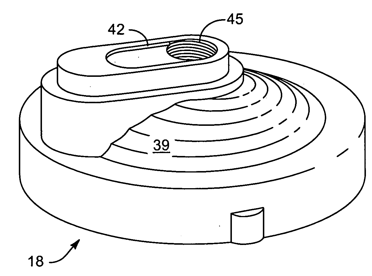
[0017]A method of the present invention is also presented for improving performance in internal combustion engines. The method in the disclosed embodiments substantially includes the steps necessary to carry out the functions presented above with respect to the operation of the described apparatus and system. In one embodiment, the method includes improving power and efficiency in a combustion process of an internal combustion engine by causing order of at least one of flow and combustion of gases in a combustion chamber. In an embodiment of the invention, the step of causing order also may include forming a multitude of streamlets along an inner surface of an engine head. These streamlets may be radial or axial, or have a combination of radial and axial components. The streamlets may be formed during combustion and / or intake, and the streamlets may have turbulent flow.
[0018]Another embodiment of the method may include improving power and efficiency in a combustion process of an internal combustion engine by forming a boundary layer in a flow gases at an engine head in a combustion cylinder by a textured inner surface of the engine head.

Problems solved by technology

This combination of squish band and hemispherical and / or bathtub shape has increased the turbulence that occurs during the compression part of the combustion cycle.
Since it is difficult to control the propagation of the flame front, a more turbulent mixing brings the combustible gases to the flame front.
Even with the progress that has been made, the amount of control and direction of combustion in a combustion chamber is still limited.

Method used


Image

  • Apparatus and method for engine head
  • Apparatus and method for engine head
  • Apparatus and method for engine head

Examples


Embodiment Construction

[0035]Reference throughout this specification to “one embodiment,”“an embodiment,” or similar language means that a particular feature, structure, or characteristic described in connection with the embodiment is included in at least one embodiment of the present invention. Thus, appearances of the phrases “in one embodiment,”“in an embodiment,” and similar language throughout this specification may, but do not necessarily, all refer to the same embodiment.

[0036]Furthermore, the described features, structures, or characteristics of the invention may be combined in any suitable manner in one or more embodiments. In the following description, numerous specific details are provided to provide a thorough understanding of embodiments of the invention. One skilled in the relevant art will recognize, however, that the invention may be practiced without one or more of the specific details, or with other methods, components, materials, and so forth. In other instances, well-known structures, ...


PUM


Abstract

An apparatus and method for improving performance in an internal combustion engine includes texturing on an inner surface of at least a portion of an engine head. The texturing may include elongated raised portions extending in one or more directions that may aid in controlling and directing pre-combustion and / or combustion gases in a combustion chamber for a more unified combustion. The result is improved power and / or efficiency.

Description

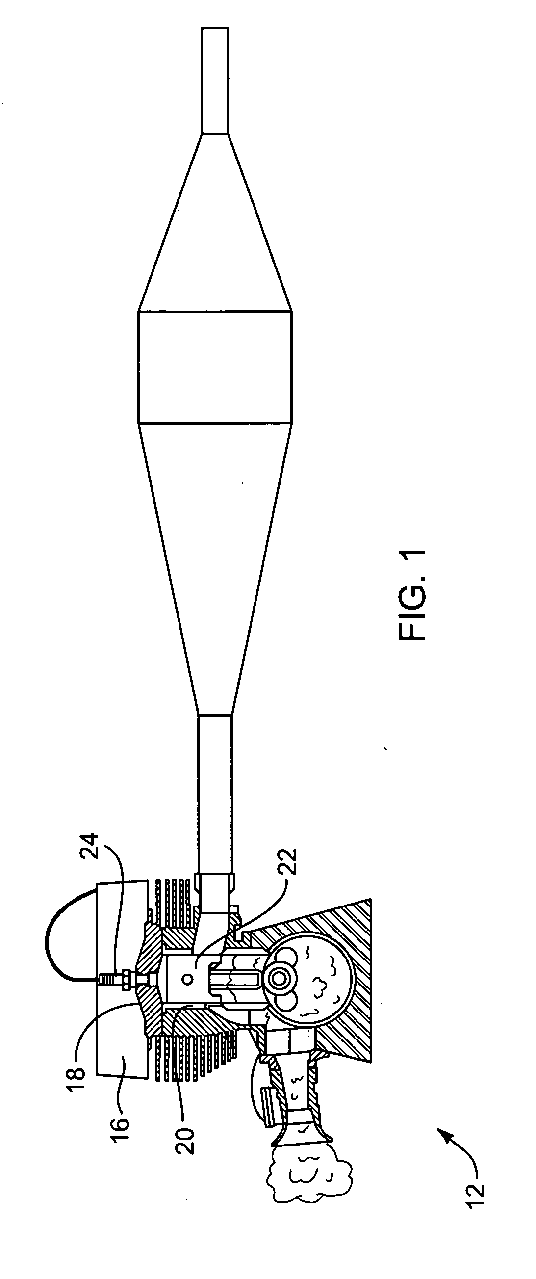
CROSS-REFERENCES TO RELATED APPLICATIONS[0001]This application claims priority to U.S. Provisional Patent Application No. 60 / 989,401 entitled APPARATUS AND METHOD FOR ENGINE HEAD and filed on Nov. 20, 2007 for Kelsey Manning and James Rex Larsen, which is incorporated herein by reference.BACKGROUND OF THE INVENTION[0002]1. Field of the Invention[0003]This invention generally relates to engine heads and more particularly to inner surfaces of engine heads that provide improved performance.[0004]2. Description of the Related Art[0005]Many workers in the art have attempted to improve performance by changing shapes of combustion chambers and by attempting to channel flow within the combustion chambers. Of particular benefit is the evolution in shape of combustion heads from a generally hemispherical shape to a configuration that includes a squish band that provides a small clearance between the engine head and the piston in a radially outer region of the head when the piston is in a top ...

Claims


Application Information

Patent Timeline
IPC IPC(8): F02F1/42
CPCF02F1/24
Inventor MANNING, KELSEYLARSEN, JAMES REX
Owner MANNING KELSEY
Learn More