
Eye Tracker with Visual Feedback

a visual feedback and eye tracking technology, applied in the field of automatic eye tracking, can solve the problems of fatigue symptoms and discomfort experienced by users, eye-controlled input interfaces imposing comparatively heavy motor tasks on the eyes of users, and known eye-controlled solutions often fail to achieve a fully satisfying user-interaction with the computer, etc., to achieve adequate information feedback, efficient and reliable, and without sacrificing the ability of users to control the events on the display

Active Publication Date: 2009-05-14
TOBII TECH AB
View PDF6 Cites 92 Cited by
  • Summary
  • Abstract
  • Description
  • Claims
  • Application Information

AI Technical Summary

Benefits of technology

[0010]The object of the present invention is therefore to provide an efficient, reliable and user-friendly eye-tracker solution, which alleviates the above problems and thus enables an adequate information feedback to the user without sacrificing the user's capabilities to control the events on the display.

Problems solved by technology

However, the known eye-controlled solutions often fail to accomplish a fully satisfying user-interaction with the computer.
One common problem is that the eye-controllable input interface imposes comparatively heavy motor tasks on the user's eyes, which are truly perceptive sensory organs.
This may lead to fatigue symptoms and discomfort experienced by the user.
Another problem is that the user, who perhaps is a handicapped person, may have problems to control his / her gaze with sufficiently high precision to control the computer as desired.
Of course, this problem is particularly accentuated if the eye-controllable screen objects are small.
Additionally, even if the user is capable of controlling his / her gaze with very high precision, imperfections in the eye-tracking equipment may introduce measurement errors in respect of an estimated point of regard on the display.
Thus, the user can abort an erroneous selection before the manipulation in respect of the object is effected.
However, it is not only difficult to adequately estimate the user's point of regard.
Another dilemma in eye tracking is that it may be problematic for the user to accomplish a selection of an on-screen object, or by other means initiate a computer-controlled action.
Expressing the user's intent to the computer via an eye-controlled interface may be difficult for many reasons.
One major issue is the fact that the eyes are designed for perception, not for motor tasks, and therefore the gaze moves over the display also when the user registers information thereon, however not is interested in generating any control commands.
A disadvantage by this approach is that the interaction process becomes relatively slow, and risk annoying the user.
However, human blinks are often unintentional, and hence the user might produce many undesired control commands.
Nevertheless this option may not be open to the user, who perhaps is incapable of manipulating such buttons / keys.
Confirmation via a voice recognition interface constitutes yet another alternative, which is less reliable, and perhaps still not a viable option for the user due to physical disablement, or factors in the environment in which the system is used, such as noise.
However, using saccades to enter data or commands via an eye-controllable input interface is problematic for other reasons.
Namely, if a saccade activates a function in respect of a particular on-screen object, typically the saccade itself results in that the user no longer observes this object, at least not directly.
Consequently, further eye-controlled manipulation of the object becomes very difficult, if at all possible.
Again, this is a problem related to the combined motor and perception tasks placed on the eyes by the eye-controllable input interface.
However, this is not straight-forward either.
Hence, regardless of how high precision the eye-tracker has, a perfect match between the user's gaze and an on-screen cursor symbol still cannot be accomplished.
Instead, any cursor symbol being directly controlled in response to an estimated point of regard is bound to introduce artifacts, which will be perceived as errors by a human user.
Naturally, this imposes separate problems, i.a. related to fitting and comfort.
However, when placing the point of regard on such a control means, the user cannot see the cursor symbol to be controlled any longer.
Nonetheless, also this strategy is problematic because it requires a mechanical input device, and it only provides one possible position for the eye controllable interface and thus offers no options for having more than one type of eye control signal.
Hence, the degree of flexibility is relatively low.

Method used


Image

  • Eye Tracker with Visual Feedback
  • Eye Tracker with Visual Feedback
  • Eye Tracker with Visual Feedback

Examples


Embodiment Construction

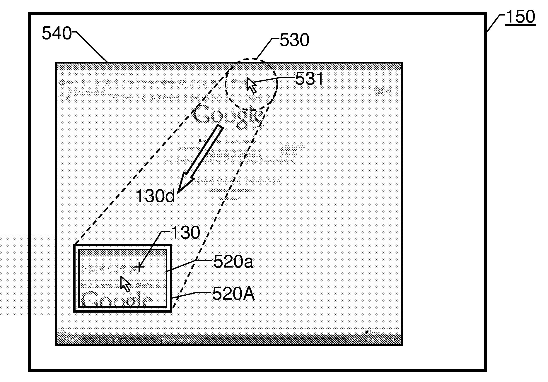
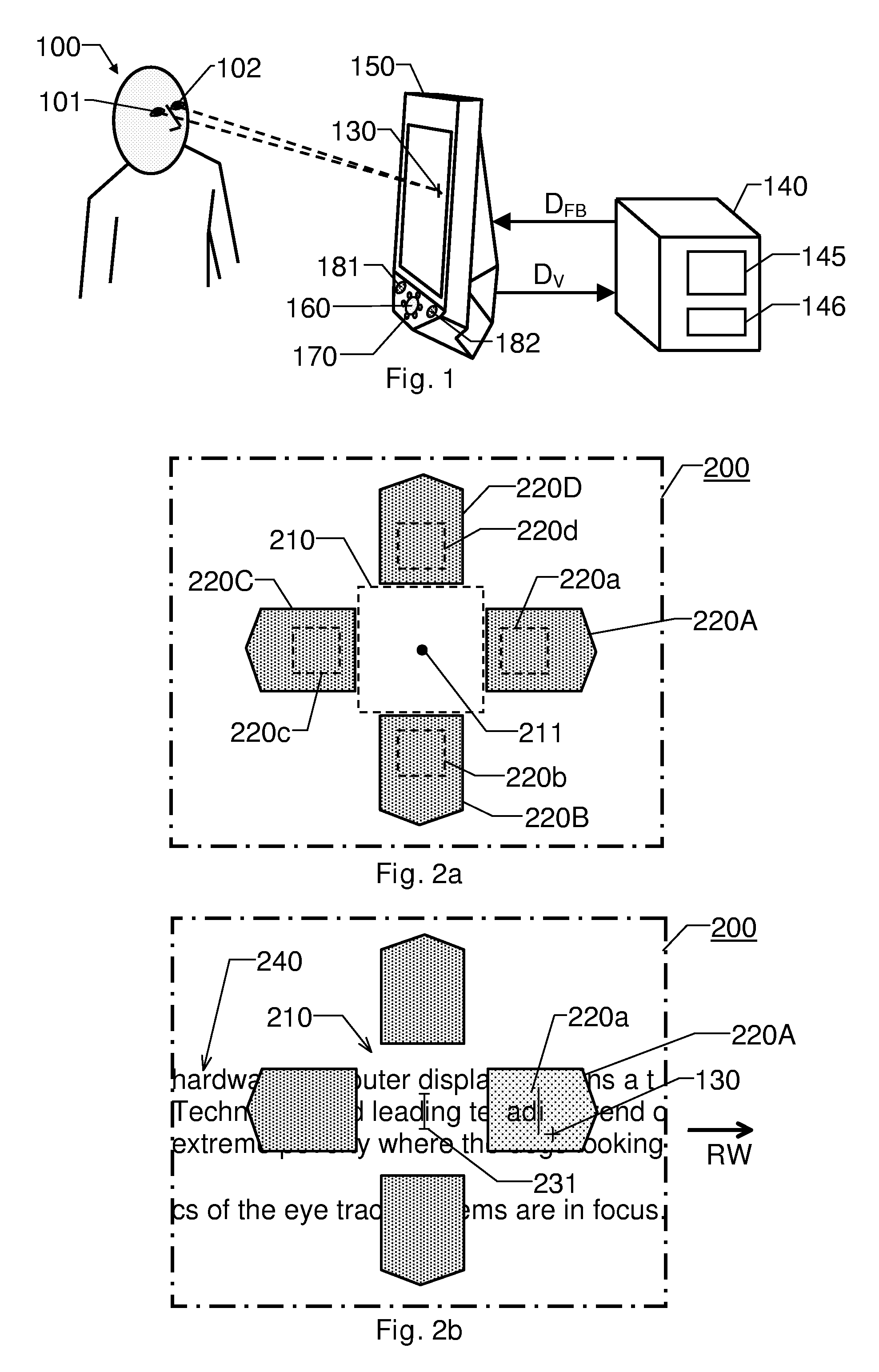
[0038]We refer initially to FIG. 1, which shows a schematic picture of an eye-tracking system according to one embodiment of the invention. The system includes a computer apparatus 140 and an associated graphical display 150. It is presumed that the computer apparatus 140 presents at least one on-screen representation of at least one GUI-component on the display 150, wherein the least one GUI-component is controllable in response to commands originated by an eye-tracker means.

[0039]The eye-tracker means includes an imaging device 160, e.g. including a video camera. Preferably, the eye-tracker means also includes one or more light sources, for instance a first set of light sources 170 located relatively proximate to an optical axis of the imaging device 160, and a second set of light sources 181 and 182 located relatively remote from the optical axis of the imaging device 160. Thereby, both bright-pupil (BP) PCCR-tracking and dark-pupil (DP) PCCR-tracking of a user's 100 eyes 101 and...


PUM


Abstract

The present invention relates to entry of control commands into a computer in response to eye-tracker detected movement sequences of a point of regard over a graphical display, which is associated with the computer. A processing module in the computer causes the display to present graphical feedback information in the form of a data-manipulating window, which visually confirms any entered control commands. The data-manipulating window is presented at a position relative to an active control object on the display, such that a center point of the window is located within a relatively small offset distance from a center point of the active control object. The window includes graphical information, which symbolizes and activity portion of the display presently being the object of an eye-tracker-controlled entry of control commands. Moreover the information in the window is repeatedly updated in response to the eye-tracker-controlled entry of control commands.

Description

THE BACKGROUND OF THE INVENTION AND PRIOR ART[0001]The present invention relates generally to automatic eye tracking wherein visual feedback information is presented to the user during operation of the eye tracker. More particularly the invention relates to a system according to the preamble of claim 1 and a method according to the preamble of claim 13. The invention also relates to a computer program according to claim 25 and a computer readable medium according to claim 26.[0002]The concept of eye tracking is well known in the art, and a number of different techniques have been developed for accomplishing automatic eye and gaze tracking. In the area of remote, non-obtrusive eye tracking, the most commonly used designs are based on so-called pupil center corneal reflection (PCCR) methods, which render it possible to determine the eyes' positions as well as their gaze direction. Thus, it is possible to estimate a point of regard, for instance on a computer display, such that based o...

Claims


Application Information

Patent Timeline
IPC IPC(8): G06F3/048
CPCG06F3/013G06F3/0481G06F3/04812
Inventor BOUVIN, JOHANRUNEMO, PER
Owner TOBII TECH AB
Learn More