Time Difference Measuring Device, Measuring Method, Distance Measuring Device, and Distance Measuring Method
a time difference measurement and measurement method technology, applied in the field of time difference measurement devices, time difference measurement methods, distance measurement devices, and distance measurement methods, can solve the problems of deteriorating measurement reliability, affecting the accuracy of distance measurement, and increasing the number of objective points in distance measurement, so as to improve accuracy and speed up the speed of distance measurement. the effect of time difference measurement and fastening the speed of distance measuremen
- Summary
- Abstract
- Description
- Claims
- Application Information
AI Technical Summary
Benefits of technology
Problems solved by technology
Method used
Image

Examples
embodiment 1
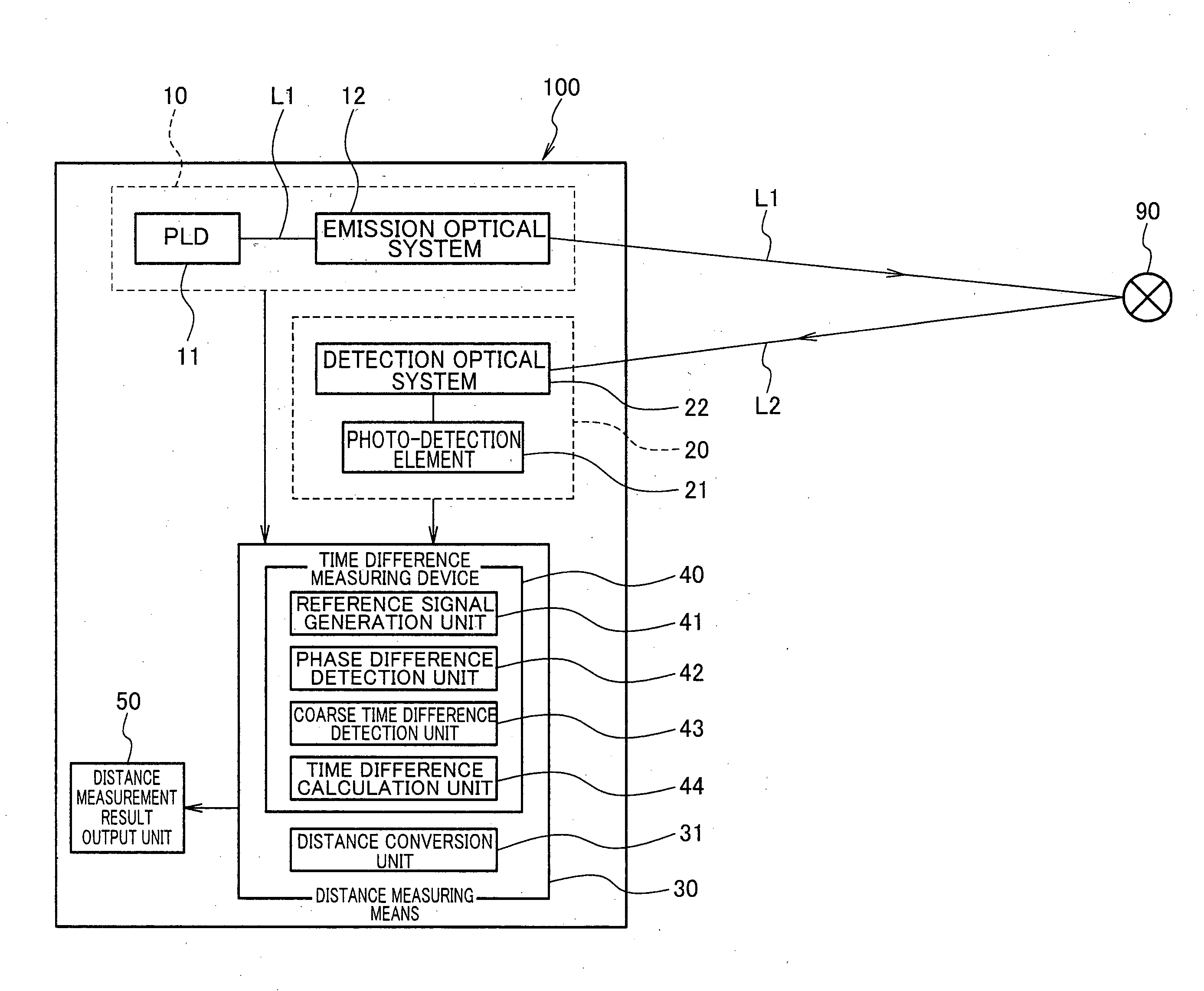
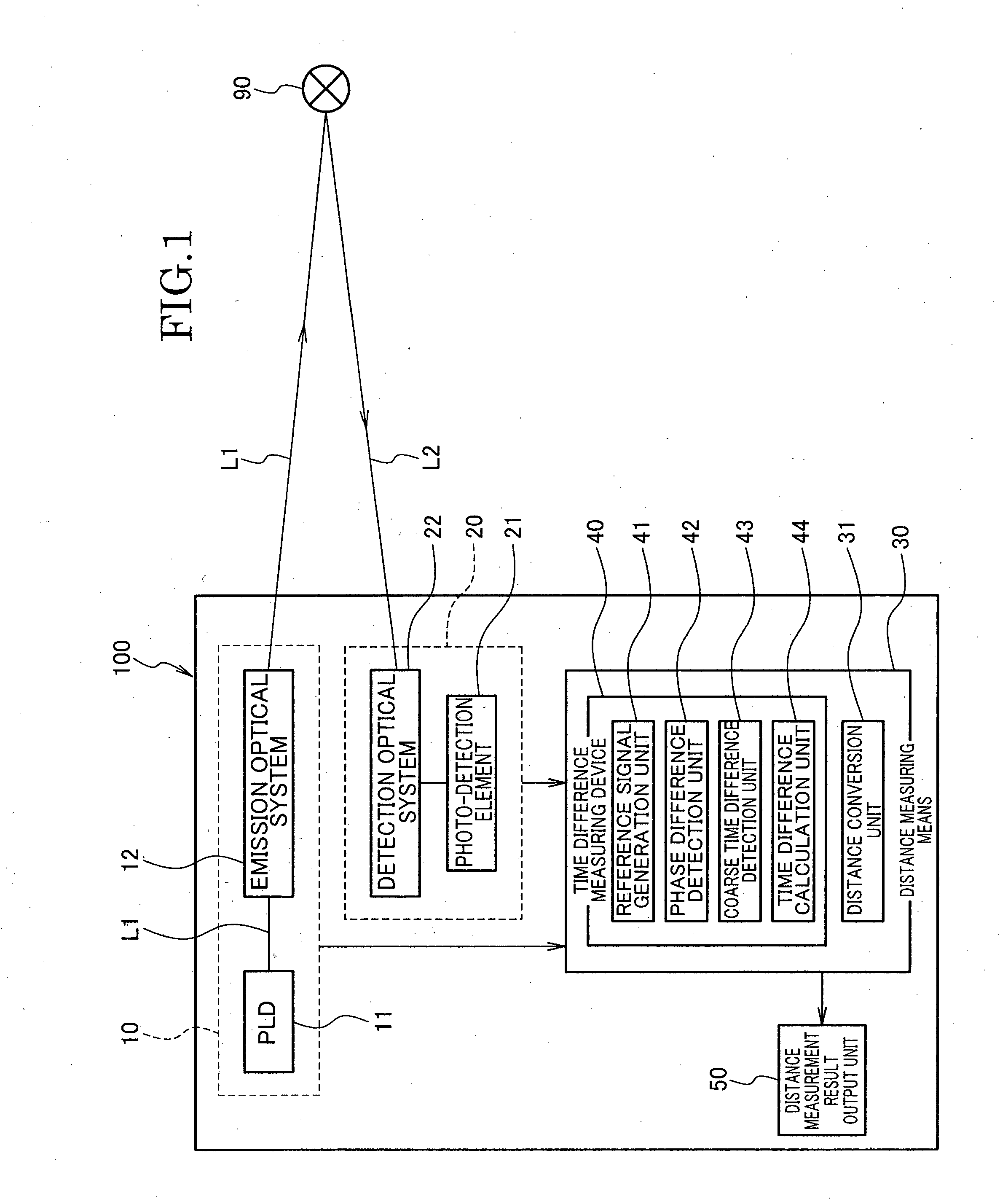
[0099]FIG. 1 is a block diagram illustrating the construction of a surveying device 100 being one embodiment of a distance measuring device according to the invention, which includes a time difference measuring device of the invention as a part of a distance measuring means.
[0100]The surveying device 100 illustrated in FIG. 1 includes a measuring light emission means 10 (measuring wave emission means) that emits a pulse laser beam L1 as a measuring wave to a distance measuring object 90, a reflected light detection means 20 (reflected wave detection means) that detects a reflected laser beam L2 (reflected wave) acquired by the laser beam L1 reflecting on the distance measuring object 90, a distance measuring means 30, and a distance measurement result output unit 50. Here, the distance measuring means 30 outputs a pulse start signal M1 (first pulse signal) at a timing of the laser beam L1 being emitted from the measuring light emission means 10, outputs a pulse stop signal M2 (secon...
modified example
[0144]The aforementioned embodiment 1 is configured such that the reference signal generation unit 41 generates one reference signal S1 of a sine wave signal and the other reference signal S2 of a cosine wave signal each separately and outputs the reference signals S1, S2 each separately, as shown in FIG. 4. However, a configuration as illustrated in FIG. 6, for example, can be applied to a modified example, wherein the reference signal generation unit 41 is not provided with the cosine wave generator (Cos) 41c, and is provided with a delay circuit 42d that applies processing to delay the sine wave reference signal S1 generated by the sine wave generator (Sin) 41b, by a time equivalent to the phase difference 90 / 2[rad] (π / 2[rad]×(2n−1); n=1, 2, . . . ) of the reference signal S1.
[0145]Originally, the reference signal generation unit 41 generates only one reference signal (sine wave signal) S1, and the delay circuit 42d generates a new reference signal with the phase of the original...
embodiment 2
[0149]FIG. 7 is a block diagram illustrating the construction of a surveying device 100′ being one embodiment of a distance measuring device according to the invention, which includes a time difference measuring device of the invention as a part of a distance measuring means.
[0150]The surveying device 100′ illustrated in FIG. 7 includes a measuring light emission means 10 (measuring wave emission means) that emits a pulse laser beam L1 as a measuring wave to a distance measuring object 90, a reflected light detection means 20 (reflected wave detection means) that detects a reflected laser beam L2 (reflected wave) acquired by the laser beam L1 reflecting on the distance measuring object 90, a distance measuring means 30′, and a distance measurement result output unit 50. Here, the distance measuring means 30′ outputs a pulse start signal M1 (first pulse signal) at a timing of the laser beam L1 being emitted from the measuring light emission means 10, outputs a pulse stop signal M2 (s...
PUM
 Abstract
Description
Claims
Application Information
 - R&D
- Intellectual Property
- Life Sciences
- Materials
- Tech Scout
- Unparalleled Data Quality
- Higher Quality Content
- 60% Fewer Hallucinations
Browse by: Latest US Patents, China's latest patents, Technical Efficacy Thesaurus, Application Domain, Technology Topic, Popular Technical Reports.
© 2025 PatSnap. All rights reserved.Legal|Privacy policy|Modern Slavery Act Transparency Statement|Sitemap|About US| Contact US: help@patsnap.com