Slot Antenna

a slot antenna and antenna technology, applied in the field of slot antennas, can solve the problems of difficult to achieve reflection-free terminal characteristics, and achieve the effect of simple structur

Inactive Publication Date: 2009-05-14
JAPAN RADIO CO LTD
View PDF3 Cites 24 Cited by
  • Summary
  • Abstract
  • Description
  • Claims
  • Application Information

AI Technical Summary

Benefits of technology

[0010]According to the present invention, a slot antenna in whic...

Problems solved by technology

Achieving a characteristic of a reflection-free terminal is difficult due to the fr...

Method used


Image

  • Slot Antenna
  • Slot Antenna
  • Slot Antenna

Examples


Embodiment Construction

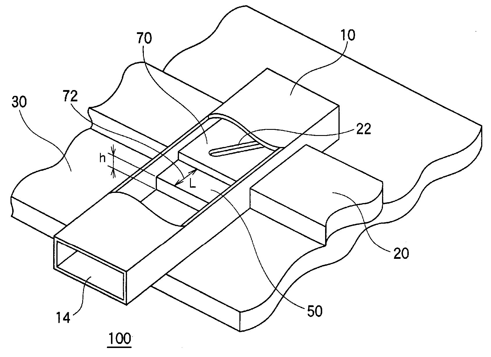
[0019]A summary will be given before describing an embodiment of the present invention. The embodiment of the present invention relates to a slot antenna. The slot antenna according to the embodiment comprises a waveguide provided with a slot for radiating electromagnetic waves. Electromagnetic waves enter the aperture plane of the waveguide, guided through the waveguide, and radiated from the slot. If impedance matching is not achieved in the aperture plane, the entering electromagnetic waves are partly reflected. Therefore, it is desirable that impedance matching be achieved in the waveguide. According to the embodiment, reflected waves are reduced by achieving impedance matching with respect to the aperture plane by providing a stairway structure in the waveguide. In this way, the energy of entering waves is efficiently turned into the energy of radiated waves. The details will follow.

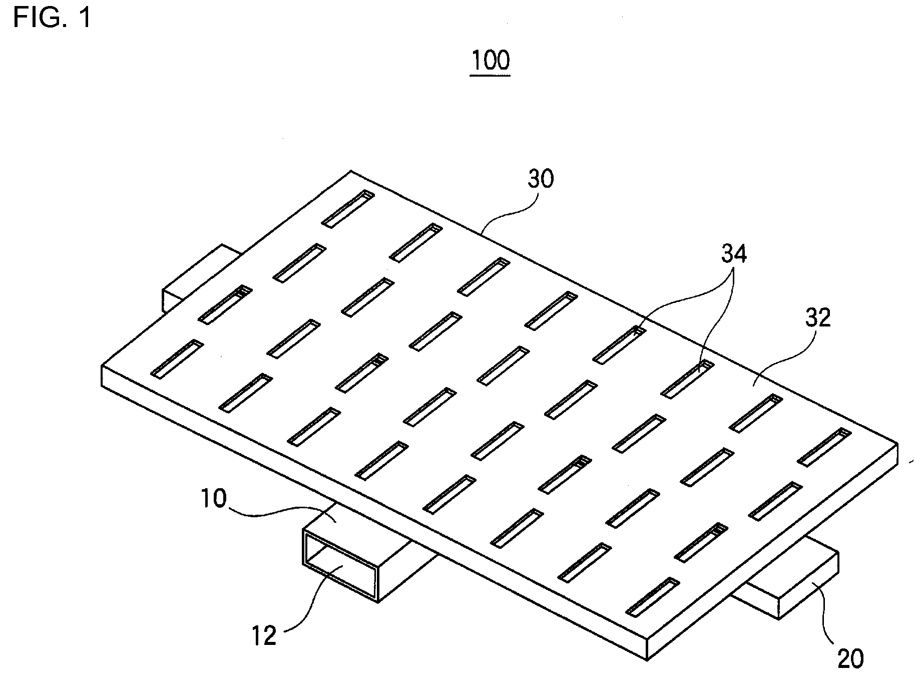
[0020]FIG. 1 is a first perspective view showing an exemplary structure of a slot antenna 100 ac...


PUM


Abstract

Impedance matching is achieved in a waveguide of a slot antenna, which is provided with an input waveguide that is fed power via an aperture plane; a stairway structure is provided in the input waveguide; the structure creates a step going upward toward a surface provided with a slot; the step difference and height of the step going upward are adjusted so that the impedance at a plane above the step and the impedance at the aperture plane match.

Description

TECHNICAL FIELD[0001]The present invention relates to an antenna technology and, more particularly, to a slot antenna comprising a waveguide provided with a slot.BACKGROUND ART[0002]Slot antennas having a waveguide provided with a slot for radiating electromagnetic waves are used for ship radars and other special-purpose radars. A slot antenna guides electromagnetic waves entering an aperture plane to the waveguide and radiates electromagnetic waves from the slot. It is desirable to achieve impedance matching in the aperture plane so that the aperture plane has a characteristic whereby the entering electromagnetic waves are totally absorbed so as not produce any reflected waves, i.e., a characteristic of a reflection-free terminal. Achieving a characteristic of a reflection-free terminal is difficult due to the frequency of electromagnetic waves, shape of the waveguide, material of the waveguide, etc. In the related art, a waveguide window or a post is provided in a waveguide in ord...

Claims


Application Information

Patent Timeline
IPC IPC(8): H01Q13/10
CPCH01P5/022H01P5/19H01Q21/064H01Q21/005H01Q13/10
Inventor SHIBUYA, YUZOSUGANO, MASAYUKI
Owner JAPAN RADIO CO LTD
Why Eureka
Try Eureka