[0008]An
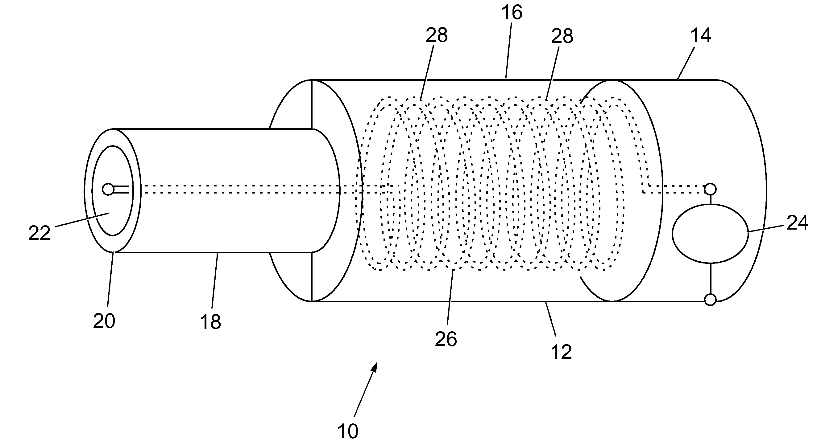
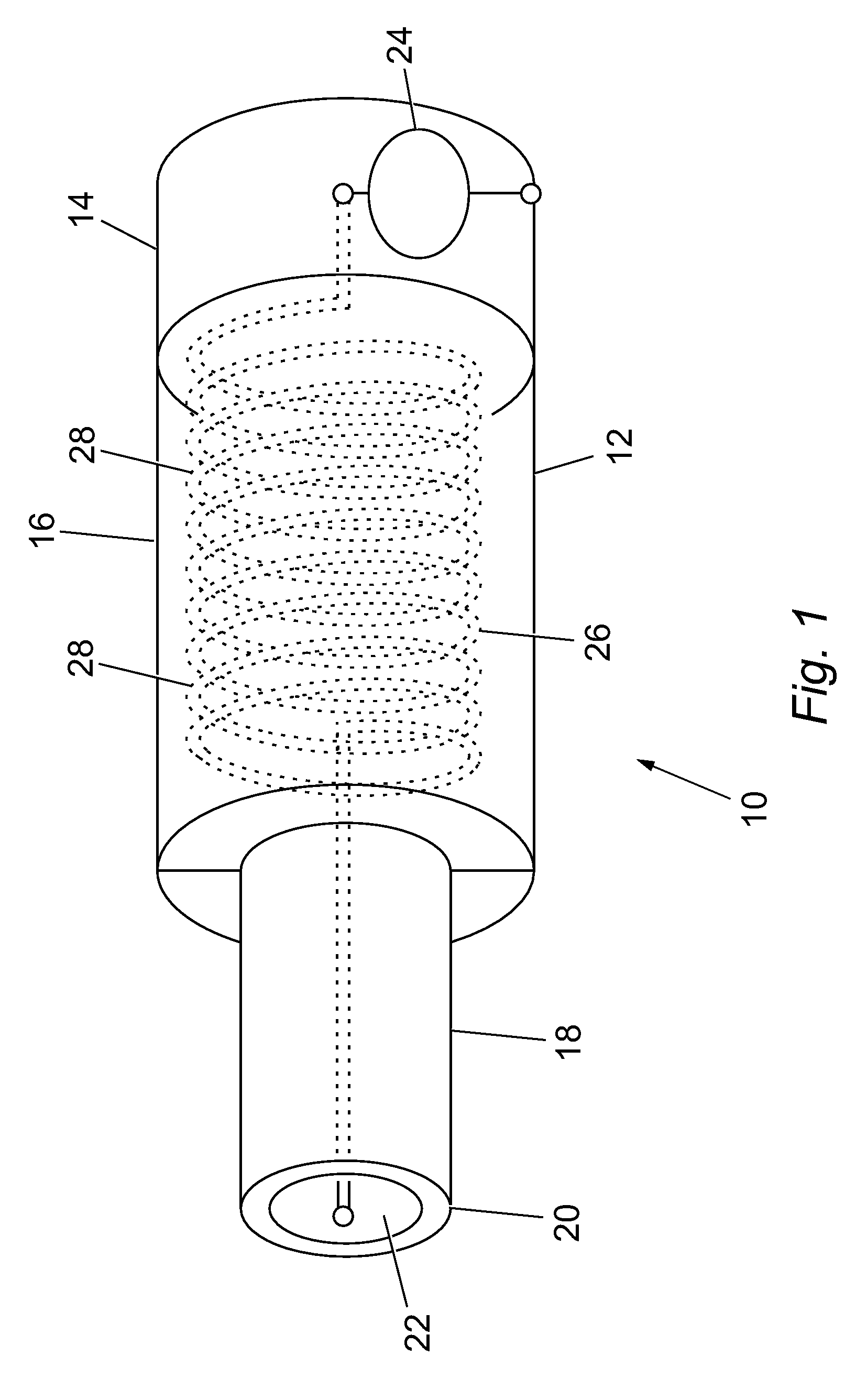
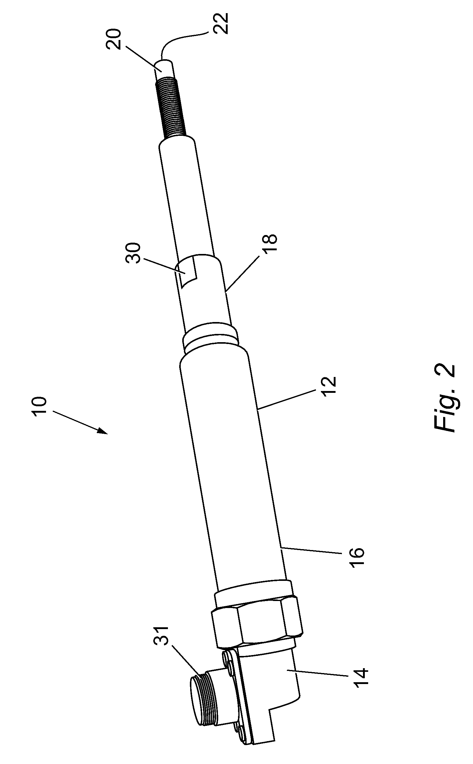
advantage of the invention lies firstly in the shape that can be achieved by the section-like sequence of generator section, inductance section, capacitance section and ignition section, namely a substantially elongate, cylindrical shape which allows easy introduction into the engine block of an
internal combustion engine, the resulting total length of the resonator assembly also being useful so that the opening in the region of the ignition section is located in a section of the
combustion chamber of the engine provided for this purpose when the resonator assembly is in the assembled state. The fact that all the above-mentioned sections are arranged in a common housing results in a shield for the electromagnetic fields that arise during operation, preventing surrounding functional units and assemblies from being influenced. But furthermore the functional units of the resonator assembly are themselves protected against any influences from the outside. For this purpose the housing is made of a conductive material or has at least one conductive surface. The need for a separate return conductor is eliminated, as the housing functions as a return conductor to the oscillatable
dipole, which is formed by the electrical series circuit comprising inductance and capacitance sections.
[0009]Advantageous embodiments of the invention are the subject of the subsidiary claims. Back-references used here indicate further development of the subject of the main claim by the characteristics of the respective subsidiary claim; they are not meant as dispensation with obtaining independent objective protection for the combinations of characteristics of the subsidiary claims to which back-reference is made.
[0010]Furthermore, with respect to interpretation of the claims with a more detailed specification of a characteristic in a subsequent claim, it must be assumed that no such restriction exists in the preceding claims.
[0011]A
mutual influence between the electrically operating components of generator section, inductance section and capacitance section can be avoided or at least reduced if these regions are arranged successively without overlap along the longitudinal axis. This facilitates firstly the
mechanical construction of the resonator assembly, e.g. such that each section can be combined in segments with the or each adjacent section, e.g. by
bolting, latching or the like, to form the resonator assembly. Secondly, undesirable mutual influences e.g. due to interactions between the resulting electromagnetic fields are reduced, so that the behaviour of the resonator assembly approaches an ideal resonator assembly with corresponding electrical components, and this can be understood with sufficient accuracy by mathematical modelling, which allows
optimum control thereof for achieving on the one hand the voltage increase in the generator and on the other hand the voltage superelevation in the resonator.
[0012]The capacitance section is preferably designed as a
metal cylinder which forms a section of the housing and of which the inner surface acts as an
electrode and the outer surface acts as part of the return conductor, so that this section of the housing performs both the mechanical and electromagnetic protective function, the function as capacitance of the oscillating circuit of the resonator and lastly also the function as return conductor for the resonator assembly as a whole. A free end of such a
metal cylinder then functions as an ignition section so that, in case of
resonance,
plasma forms within this free end, in particular directly in the
edge region of the free end.
[0013]Preferably an inductance encompassed by the inductance section with a plurality of coil turns is oriented in such a way that a
magnetic field which forms within the inductance during operation of the resonator assembly is coaxial with the longitudinal axis of the resonator assembly. For this purpose the coil turns are arranged on an (imaginary) cylinder wall all in the same plane. With respect to the design of the resonator assembly, the inductance therefore contributes substantially to its length; a
diameter, that is, a width, and a depth of a surrounding enveloping contour remains small compared with the total length, so that the resonator assembly as a whole assumes a tubular contour, which makes it easier to introduce it into the engine block, sections located within the engine block when assembled being protected by the latter in addition. The generator section includes an electronic
system which operates to excite the inductance and capacitance sections, connections for their external supply being passed through the housing. The electronic
system is also protected electromagnetically and mechanically by the housing, so that when the oscillating circuits encompassed by the resonator assembly are excited, the function of the electronic
system is not affected by external magnetic fields which would otherwise have a disturbing influence on these circuits. If the connections for external supply to the electronic system are passed through the housing, an opening in the housing which is necessary for external supply to the electronic system is limited to a minimum.
