Liquid crystal display device

Active Publication Date: 2009-05-07
PANASONIC LIQUID CRYSTAL DISPLAY CO LTD +1
View PDF6 Cites 11 Cited by
  • Summary
  • Abstract
  • Description
  • Claims
  • Application Information

AI Technical Summary

Benefits of technology

[0033]To simply explain advantageous effects acquired by the typical inventions among the inventions described in this specification, they are as follows.

Problems solved by technology

Accordingly, when an absorption axis of a polarizer on a viewer's side becomes orthogonal to the absorption axis of the polarization sunglasses, when a viewer wears the polarization sunglasses, there arises a situation where the viewer cannot observe an image.
Further, even when the absorption axis of the polarizer is slightly displaced from the direction orthogonal to the absorption axis of the polarization sunglasses, there arises a drawback that a display is darkened.
By arranging the absorption axis of the polarizer on a viewer's side and the absorption axis of the polarization sunglasses parallel to each other, such a drawback that a display is darkened can be obviated.
In this case, however, when the viewer wears the polarization sunglasses, there arises a drawback that a display becomes darkened either before or after the rotation of the liquid crystal display panel.
However, in case of the liquid crystal display panel adopting an IPS-method, due to reasons such as a control of the rotational directions of the liquid crystal molecules, it is necessary to incline the alignment axes of the first alignment film and the second alignment film by a pre-twist angle with respect to the extension direction of the linear portions of the pixel electrode (PX) thus giving rise to a drawback peculiar to the liquid crystal display panel of IPS-method that the direction of the absorption axis adopting the polarizer on a viewer's side cannot be arranged irrelevant to the extension direction of the linear portions of the pixel electrode.
However, such structure merely inclines the absorption axis of the polarizer on a viewer's side by 10° or 15° which constitutes the pre-twist angle from the direction of 0° or 90° and hence, such pixel structure may be insufficient in inclination.
Accordingly, when the pixel has the multi domain structure, it is more difficult to cope with drawbacks attributed to polarization sunglasses compared to the pixel which has the single domain structure.

Method used


Image

  • Liquid crystal display device
  • Liquid crystal display device
  • Liquid crystal display device

Examples


embodiment 1

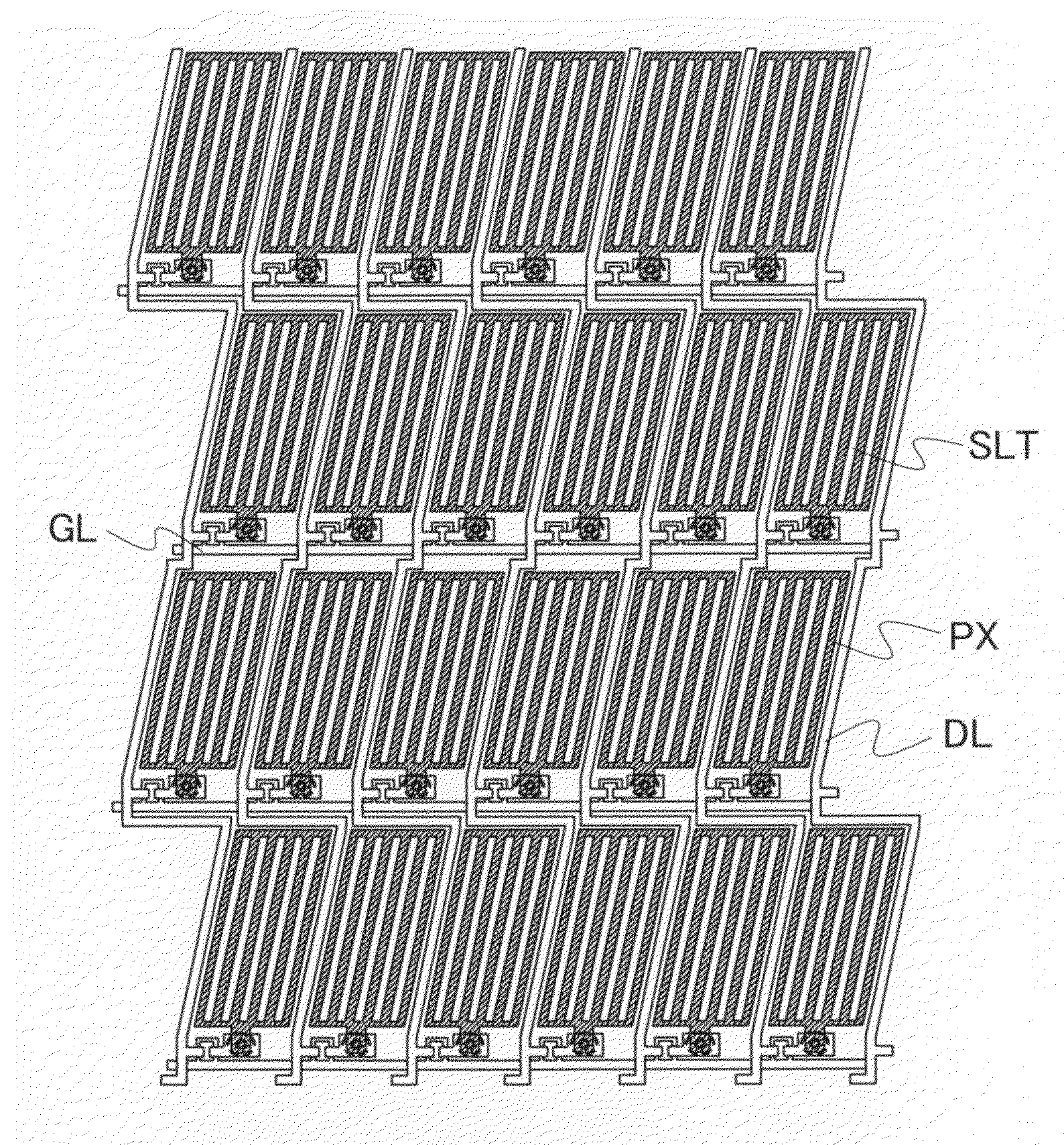
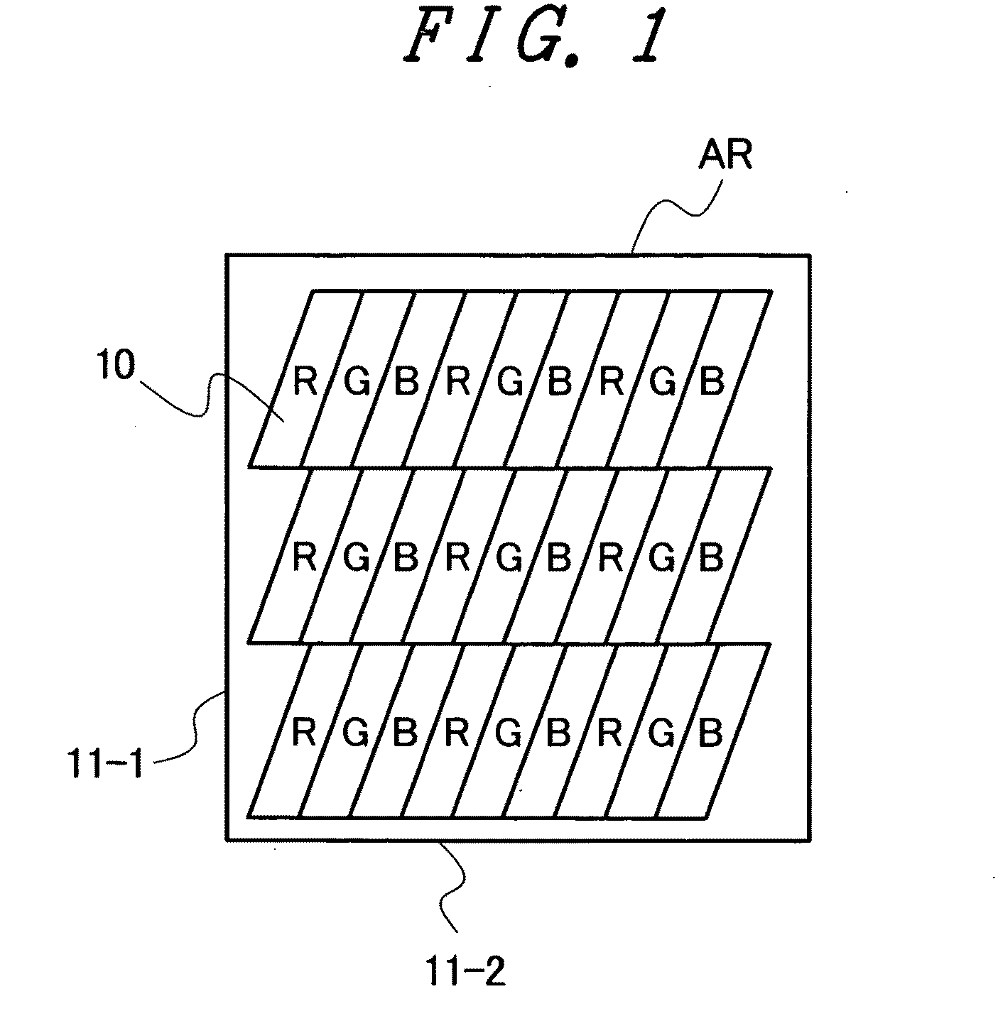
[0056]FIG. 1 is a schematic view showing the pixel arrangement of a liquid crystal display panel according to an embodiment 1 of the present invention. The pixel arrangement of the conventional liquid crystal display panel is shown in FIG. 19 for a comparison purpose with the pixel arrangement of the liquid crystal display panel of this embodiment.

[0057]In the conventional liquid crystal display panel shown in FIG. 19, sub pixels 10 having a rectangular shape are arranged within a display region (AR) in the longitudinal direction as well as in the lateral direction. On the other hand, in the liquid crystal display panel of this embodiment, sub pixels 10 having a parallelogram shape are arranged within a display region (AR) in the longitudinal direction as well as in the lateral direction.

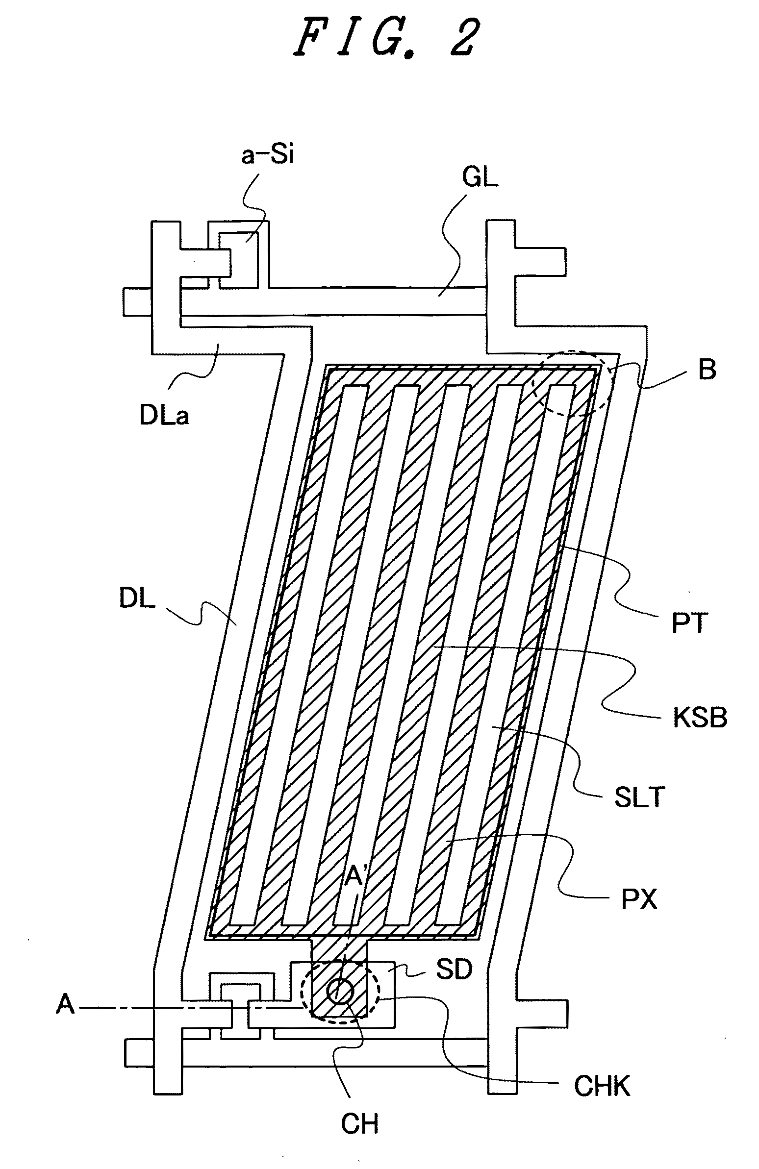
[0058]FIG. 2 is a schematic plan view for explaining the electrode structure of the liquid crystal display panel according to the embodiment 1 of the present invention. As shown in FIG. 2, in this e...

embodiment 2

[0114]FIG. 11 is a schematic view showing the pixel arrangement of a liquid crystal display panel according to an embodiment 2 of the present invention.

[0115]In the above-mentioned embodiment, linear portions of a pixel electrode (PX) extend in the direction along long sides out of long sides and short sides of each sub pixel. On the other hand, in this embodiment, linear portions of a pixel electrode (PX) extend in the direction along short sides out of long sides and short sides of each sub pixel.

[0116]The liquid crystal display panel of this embodiment differs from the liquid crystal display panel of the above-mentioned embodiment with respect to a point that the scanning lines (GL) are inclined. Accordingly, also in the liquid crystal display panel of this embodiment, sub pixels 10 having a parallelogram shape are arranged in the longitudinal direction as well as in the lateral direction.

[0117]FIG. 12 is a schematic plan view for explaining the electrode structure of the liquid ...

modification 1

of Embodiment 2

[0124]When the liquid crystal layer (LC) is made of negative liquid crystal, in the same manner as the above-mentioned embodiment, in place of the angle φ3, in accordance with the arrangement shown in FIG. 8, an angle (angle Φ3 not shown in the drawing) from the second direction (x) to the direction orthogonal to the alignment axis of the second alignment film (AL2) (the direction indicated by G in FIG. 8) may be used.

[0125]In the same manner, in place of the above-mentioned angle φ5, an angle (angle Φ5 not shown in the drawing) which is a narrow-side angle out of intersection angles between the second direction (x) and a direction (G in FIG. 8) orthogonal to the alignment axis (C in FIG. 8) of the first alignment film (AL1) and is measured in the clockwise direction from the second direction (x) may be used.

[0126]The angles Φ3 and Φ5 may be also measured within a range from −90° to +90°.

[0127]Accordingly, the above-mentioned formulae (3) are expressed by the followin...


PUM


Abstract

An absorption axis of a polarizer on a viewer's side is set to an arbitrary direction to cope with problems attributed to polarization sunglasses or the like. Video lines extend in a reference direction as a whole while being bent locally. Assuming a narrow-side angle out of intersection angles between the reference direction and the extension direction of a portion of the video line as θ1, assuming a narrow-side angle out of intersection angles between the reference direction and the extension direction of the linear portions of the first electrode as θ2, assuming a narrow-side angle out of intersection angles between the reference direction and an alignment axis of the second alignment film as θ3, assuming a narrow-side angle out of intersection angles between the reference direction and an absorption axis of the second polarizer as θ4, and in measuring the angles θ1, θ2, η3 and θ4 within a range from −90° to +90° from the reference direction while setting a clockwise direction as a normal direction, all of a sign of the angle θ1, a sign of the angle θ2 and a sign of the angle θ3 are equal in one sub pixel, the angles θ1 of all sub pixels have the same sign, and the formulae (1) 10°≦|θ1|≦|θ3| and 10°≦|θ2|≦θ3|; (2) 0°≦|θ3−θ2|≦20°; (3) 0°≦|θ1−θ2|≦2°; (4) 10°≦|θ3|≦80°; and (5) 0°≦|θ3−θ4|≦2° or 88°≦|θ3−θ4|≦92° are satisfied in all sub pixels.

Description

[0001]The present application claims priority from Japanese application JP2007-285100 filed on Nov. 1, 2007, the content of which is hereby incorporated by reference into this application.BACKGROUND OF THE INVENTION[0002]1. Field of the Invention[0003]The present invention relates to a liquid crystal display device, and more particularly to a liquid crystal display device which includes a means for overcoming problems attributed to polarization sunglasses.[0004]2. Description of the Related Art[0005]A TFT-type liquid crystal display panel which uses a thin film transistor as an active element can display a high-definition image and hence, such a liquid crystal display panel has been used as a display device of a television receiver set, a personal computer display or the like. Particularly, a miniaturized TFT-type liquid crystal display device has been popularly used as a display part of a mobile phone.[0006]On the other hand, as such a TFT-type liquid crystal display panel, a verti...

Claims


Application Information

Patent Timeline
IPC IPC(8): G02F1/1335G02F1/1343
CPCG02F1/134336G02F2001/133531G02F1/134363G02F1/133531
Inventor YAMADA, YASUYUKIMORIMOTO, MASATERU
Owner PANASONIC LIQUID CRYSTAL DISPLAY CO LTD
Why Eureka
Try Eureka