
LED signaling apparatus with infrared emission

Inactive Publication Date: 2009-05-07
BWTEK LIGHTING
View PDF47 Cites 44 Cited by
  • Summary
  • Abstract
  • Description
  • Claims
  • Application Information

AI Technical Summary

Benefits of technology

[0012]The LED signaling apparatus features low power consumption and ruggedness to adapt for harsh environment conditions since it is completely comprised of solid state elements. The LEDs may be powered by rechargeable batteries for quick field deployment.

Problems solved by technology

The portable design of the disclosed signal beacon is not suitable for permanent or semi-permanent navigational applications where a much higher light intensity is required.
Due to the fact that the disclosed the lighting fixture still comprises lamp based light sources, it suffers similar disadvantage as conventional lamp based navigational lights.

Method used


Image

  • LED signaling apparatus with infrared emission
  • LED signaling apparatus with infrared emission
  • LED signaling apparatus with infrared emission

Examples


Embodiment Construction

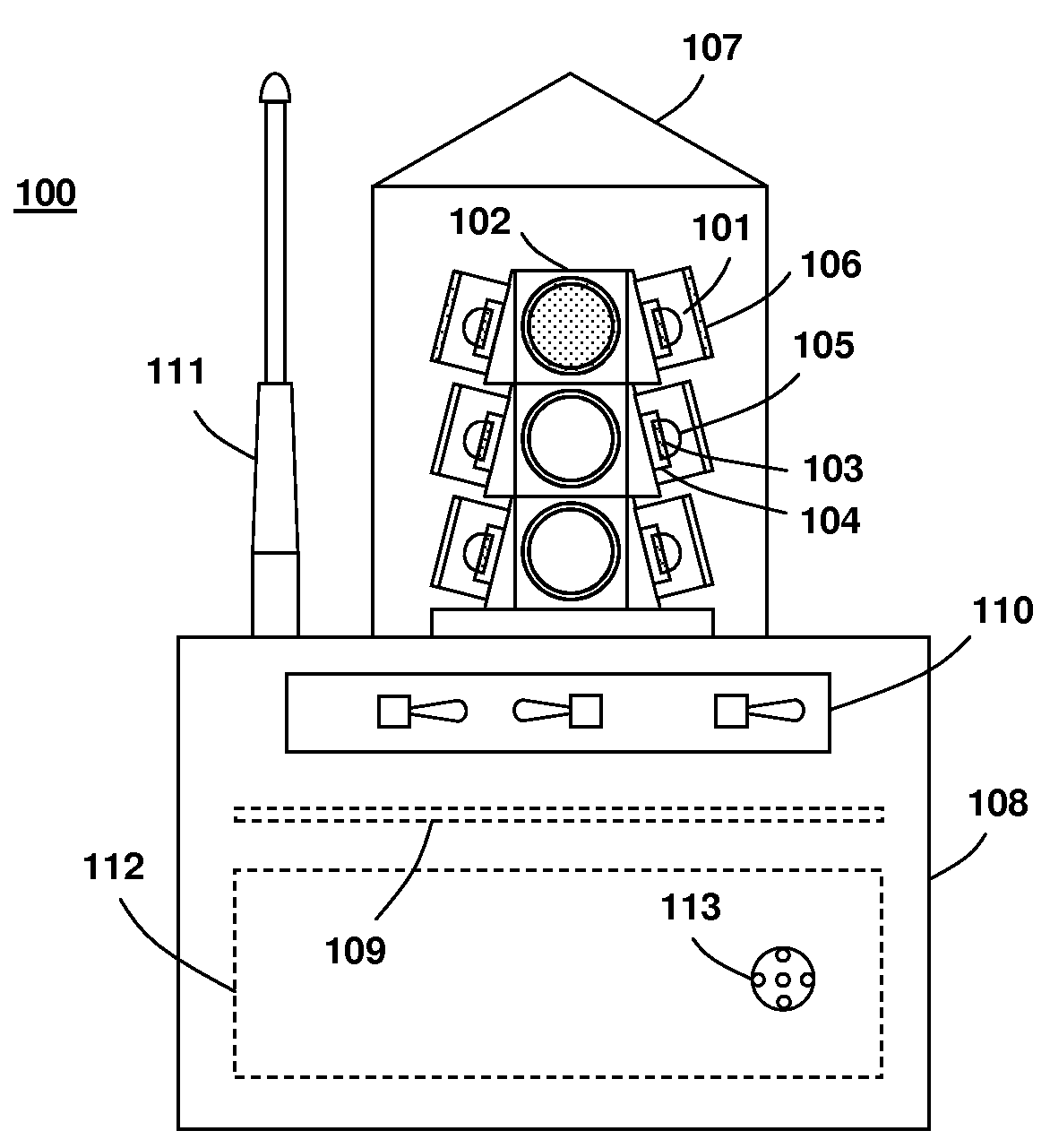
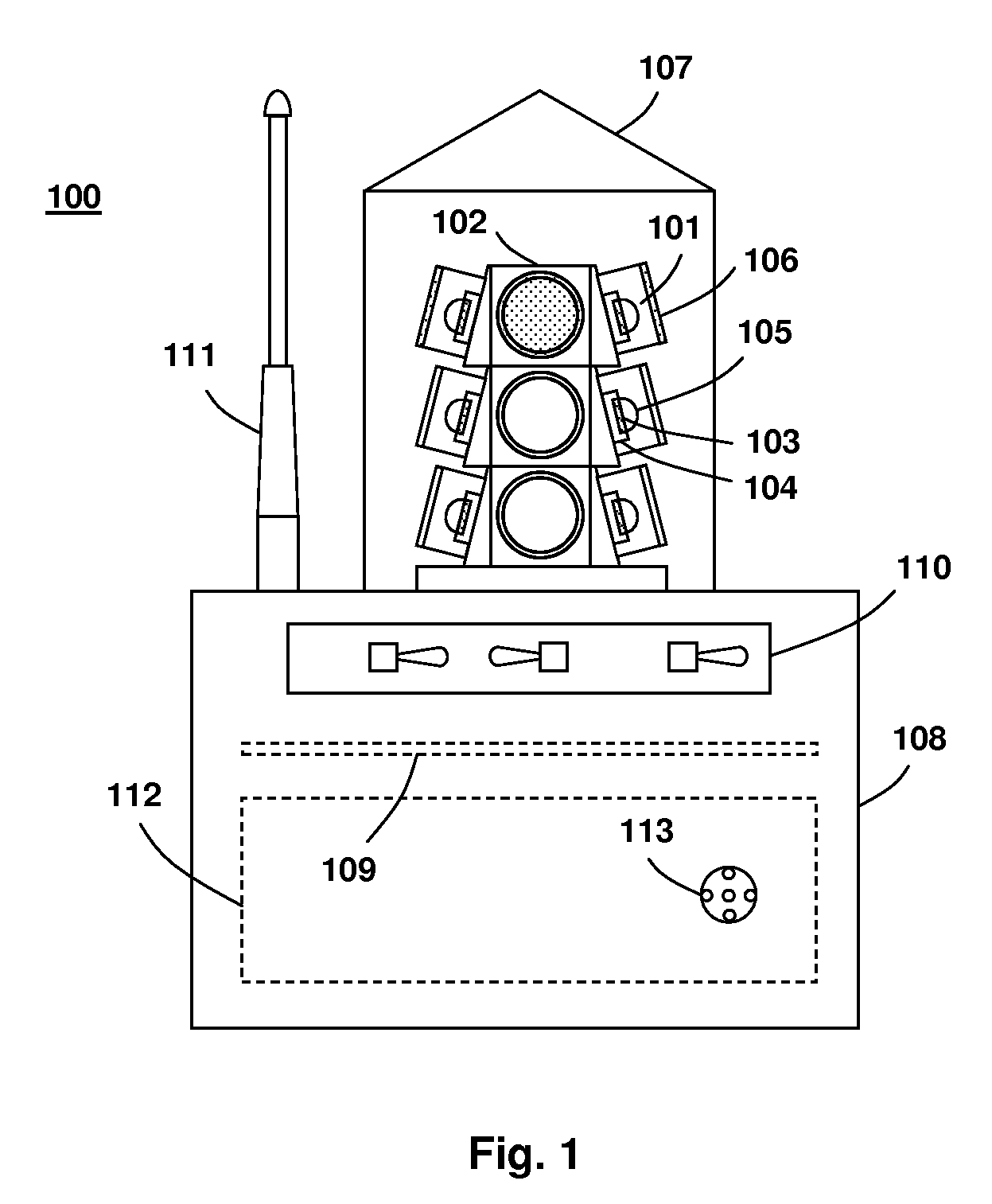
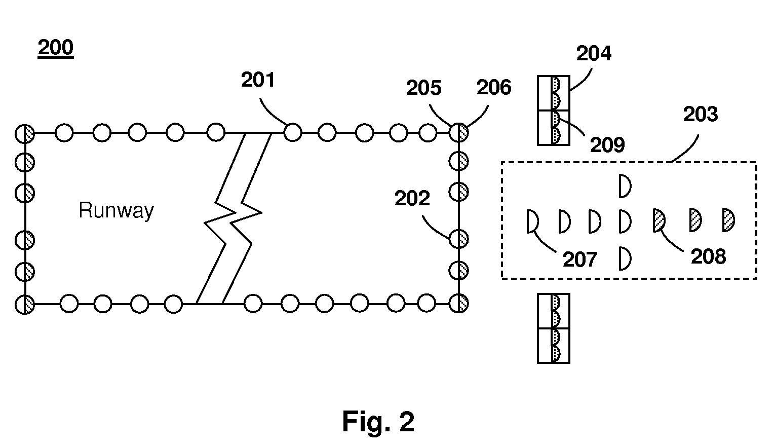
[0018]Before describing in detail embodiments that are in accordance with the present invention, it should be observed that the embodiments reside primarily in combinations of method steps and apparatus components related to an LED signaling apparatus with infrared emission. Accordingly, the apparatus components and method steps have been represented where appropriate by conventional symbols in the drawings, showing only those specific details that are pertinent to understanding the embodiments of the present invention so as not to obscure the disclosure with details that will be readily apparent to those of ordinary skill in the art having the benefit of the description herein.

[0019]In this document, relational terms such as first and second, top and bottom, and the like may be used solely to distinguish one entity or action from another entity or action without necessarily requiring or implying any actual such relationship or order between such entities or actions. The terms “comp...


PUM


Abstract

An infrared signaling apparatus is disclosed, which utilizes high intensity solid state lighting elements, such as light emitting diodes (LEDs) to provide signaling for navigational as well as search / rescue applications employing night vision equipments.

Description

REFERENCE TO RELATED APPLICATIONS[0001]This application claims an invention which was disclosed in Provisional Patent Application No. 60 / 767,489, filed Apr. 11, 2006, entitled “Infrared LED Lighting Apparatus for Night Vision Based Navigation”, and in Provisional Patent Application No. 60 / 767,526, filed May 15, 2006, entitled “LED Signaling Apparatus with Infrared Emission”. The benefit under 35 USC §119(e) of the above mentioned U.S. Provisional Applications is hereby claimed, and the aforementioned applications are hereby incorporated herein by reference.FIELD OF THE INVENTION[0002]This invention generally relates to a signaling apparatus, and more specifically to a navigational LED signaling apparatus with infrared emission.BACKGROUND[0003]Lighting / signaling systems are important navigational aids for aircrafts, boats, or other vehicles, in providing guidance, signaling, and demarcation functions therefore. Semiconductor light emitting devices, preferably light emitting diodes (L...

Claims


Application Information

Patent Timeline
IPC IPC(8): H05B37/04
CPCB63B45/02B63B45/04H05B33/0803F21W2111/06F21Y2101/02F21W2111/047F21Y2115/10H05B45/3577H05B45/345
Inventor WANG, SEAN XIAOLU
Owner BWTEK LIGHTING
Learn More