
Lock for coin deposit container

a technology for storing containers and coins, applied in the field of container locks, can solve the problem that the bolt cannot be moved by the coin, and achieve the effect of preventing the bolt from being moved by the coin

Inactive Publication Date: 2009-05-07
SCHULTE SCHLAGBAUM
View PDF3 Cites 2 Cited by
  • Summary
  • Abstract
  • Description
  • Claims
  • Application Information

AI Technical Summary

Benefits of technology

[0007]It is proposed, first and essentially, that the scanning device should be configured as a fixing jaw that firmly prevents the coin that is entering the insertion shaft in the scanning position while still partially accessible from outside from being withdrawn with the bolt pre-locked. According to the invention the coin is inserted into the insertion shaft of the lock housing as far as the scanning position. In this scanning position the scanning device scans the diameter of the coin. The position here is a maximum insertion depth in which the coin can still be gripped from outside but, because of the fixing function of the fixing jaw, cannot be withdrawn from the insertion shaft. The coin is preferably held in a form-locking mounting in the scanning position. The coin is thus preferably partially surrounded as if by a pincer, so that a fixing jaw is configured by an oscillating lever that can rotate around an axle in the housing. An additional fixing jaw can be combined firmly with the housing. The two fixing jaws surround the coin beyond its area of maximum diameter, so that it can be withdrawn again only from the insertion shaft after a separating motion of the two fixing jaws. No actuation of the bolt occurs with the coin itself. Said bolt can preferably be displaced perpendicularly to the coin-inserting direction. The oscillating lever preferably comprises a support arm, on whose ends the axle is fulcrumed. The fixing jaw preferably extends down from the supporting limb in an essentially perpendicular direction. The oscillating lever forms a rotation recess flanked by at least one blocking flank. A rotation stud attached to the bolt can engage in this rotation recess when an appropriate coin is inserted into the insertion shaft. A guide groove can connect with the rotation recess. Said guide groove extends, when an appropriate coin is inserted, in a direction essentially parallel to the displacement direction of the bolt. While the movable fixing jaw extends essentially perpendicular to the displacement direction of the bolt, the supporting limb extends parallel to the displacement direction of the bolt. The stationary fixing jaw can become movable. It can be secured to the lock housing, for instance by means of screws. By releasing the screws, the distance between the fixing jaws can be adjusted in the release position. The insertion shaft preferably comprises a convexity in which a portion of the inserted coin is located. The convexity extends over a surface that is large enough so that the coin can be grasped between two fingers to allow it to be extracted from the insertion shaft. Essentially the coin is inserted into the insertion shaft only for scanning its diameter. While the coin is being inserted, only the blocking device is displaced from a blocking position into a release position. No bolt displacement is possible by means of the coin. In an elaboration of the invention, the lock housing comprises a blocking element. Said blocking element is accessible from the housing exterior. Said blocking element is capable of fixing the oscillating lever or the rotation recess in a position in which the rotation recess lies in the path of the rotation stud. Thus, when blocked, the lock can be actuated without deposit function. The blocking element can take the form of a blocking stud, which in blocked position engages in an end portion of the guide groove that connects with the rotation recess, in order to make the oscillating lever stationary in the rotation position corresponding to the release position. The bolt pre-locking occurs in known manner by means of a crankshaft, which is actuated by a handle. Said crankshaft engages in an engagement opening of the bolt in order to pre-lock the bolt. The lock, in addition, comprises a blocking device with which the bolt can be kept in the pre-closed position. The blocking device, in addition, can also hold the bolt in the re-locked position. The blocking device can be brought from a blocked position into a release position. This can occur in known manner, for instance by actuating a key. However, the blocking device is preferably released by reading an electronic secret code, and the secret code is kept in a transponder, which in known manner is read by the closing device. In addition it can be foreseen that the secret code is a PIN, which is entered by a keyboard. In addition, the lock can comprise a fingerprint reading device in order to read a user's fingerprint. Upon correctly entering the secret code, the blocking device is displaced into the release position. The bolt can be pre-locked. The blocking device holds it in the pre-locked position until the correct secret code is again entered. The lock can include a cashier function. For this purpose the lock can be opened with an overriding secret code. In the re-closed bolt position, the coin can be withdrawn. By means of an auxiliary tool that is inserted into the insertion shaft, the two jaws are moved apart to the correct distance, so that the rotation stud can engage in the rotation recess. The fixing jaw can be temporarily blocked in this position by means of the blocking device. It is foreseen that, when the bolt is completely pre-locked, the rotation stud can move the blocking device out of the blocked position. This can occur by pressure on the blocking pin. Said blocking pin is then moved out of the guide groove. The oscillating lever can also be made stationary by means of a screw. For this purpose the oscillating lever, and in particular the fixing jaw formed by the oscillating lever, can configure a screw-in opening into which the screw can be inserted and turned. As a result, the scanning device can be put out of operation for an extended period so that the lock can also be operated without deposit function. In an elaboration of the invention it is foreseen that the scanning device interacts with an electric scanner or a switch. Depending on the actuation position of the scanning device, an electric circuit is closed or opened. As a result an electric signal can be provided, which changes its condition when an appropriate coin is inserted into the insertion shaft. This electric signal can be used to block or release the bolt. For this purpose it is possible to use an electric magnet that can be already situated in the lock housing. Said magnet can be moved into a release position when the scanning device emits a corresponding electric signal. In an elaboration of the invention it is foreseen that the coin diameter is immediately scanned by a scanner.

Problems solved by technology

No bolt displacement is possible by means of the coin.

Method used


Image

  • Lock for coin deposit container
  • Lock for coin deposit container
  • Lock for coin deposit container

Examples


Embodiment Construction

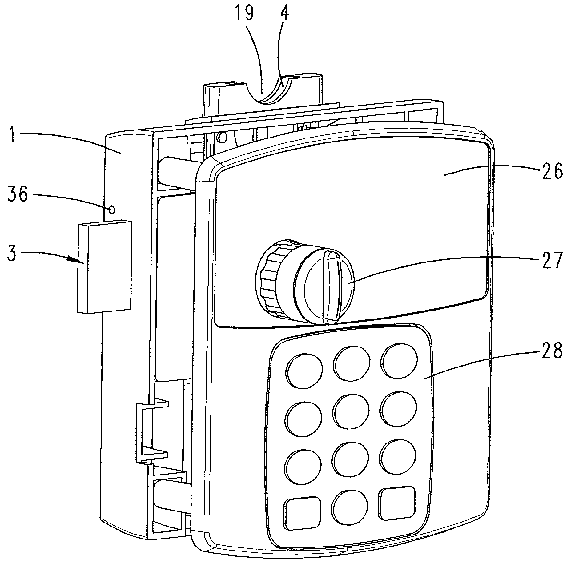
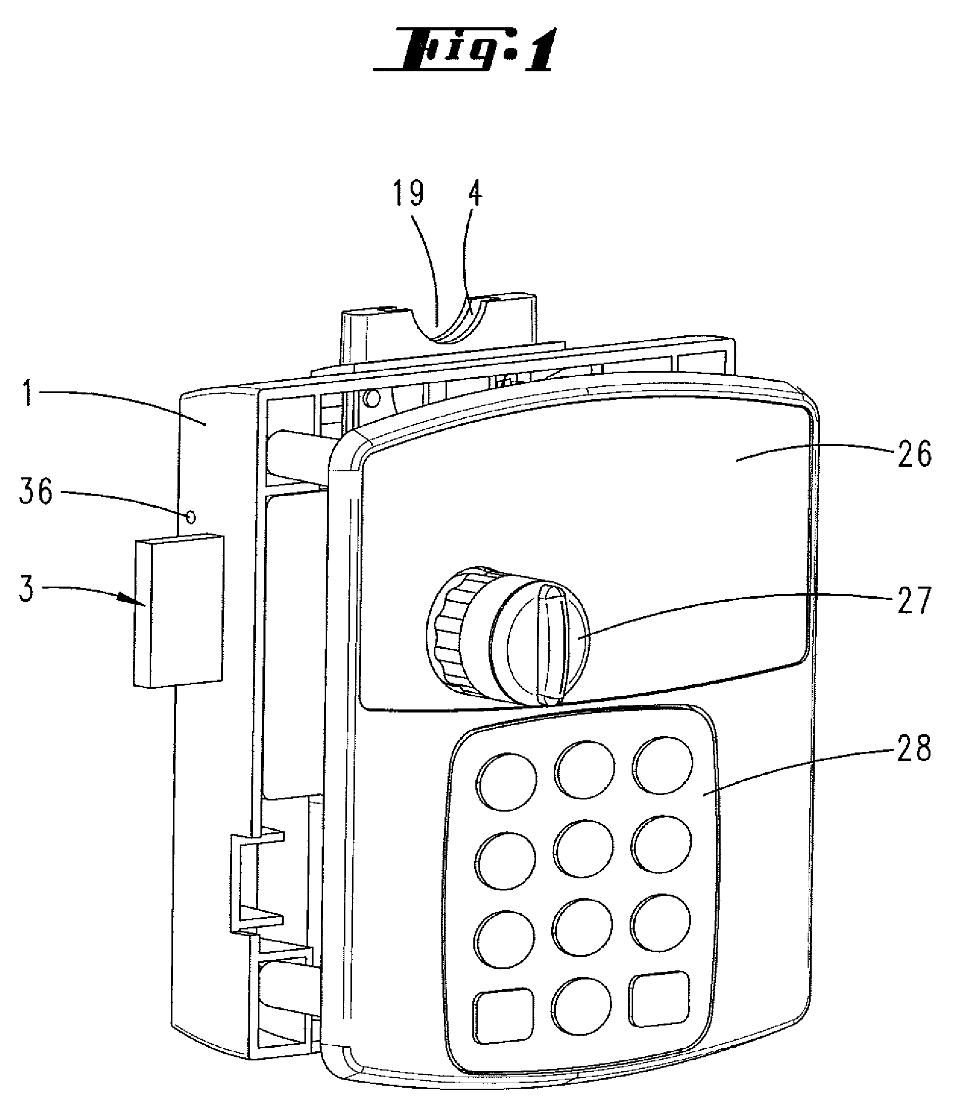
[0019]The container lock shown in the illustrations can be affixed to a container door 25. It comprises a housing 1, which can be affixed to the container door 25 on the inside of the container. The lock comprises a front plate 26, which is affixed on the outside of the door. The front plate 26 comprises a handle 27 by which a crankshaft 24 can be rotated in order to displace a bolt 3 positioned in the housing 1 in a direction that displaces the bolt. The front plate 26 also comprises a scanning field 28 by which a numeric code can be entered.

[0020]A transponder reading device can also be installed in the front plate 26 or in the handle 27 in order to read a transponder. In addition, the lock can also be connected with a fingerprint reading device.

[0021]The housing 1 consists of a synthetic material. The bolt 3 is preferably of metal construction. Found on the underside of the bolt is a blocking slot 30 that forms two blocking steps 31, 34. A blocking extension 32 of a blocking leve...


PUM


Abstract

A container lock with a housing and, positioned in it, a bolt that can be displaced by actuating a handle, with an insertion shaft for inserting a coin, with a scanning device for scanning the diameter of the coin inserted into the insertion shaft as far as a scanning position, where the scanning device interacts with a blocking device in such a way that the bolt can be displaced only with a coin having a correct diameter. It is proposed that the scanning device should configure a fixing jaw, which securely grips the coin that is inserted in the insertion shaft so that it is partly accessible from outside in the scanning position with the bolt pre-locked to prevent its withdrawal.

Description

FIELD OF THE INVENTION[0001]The invention relates to a container lock with a housing and within it a bolt that can be displaced by actuating a handle, as well as with an insertion shaft for inserting a coin, with a scanning device for scanning the diameter of the coin inserted in the insertion shaft as far as a scanning position, so that the scanning device interacts with a blocking device in such a way that the bolt can be displaced only for a coin having a correct diameter.BACKGROUND OF THE INVENTION[0002]A container lock of this type is known in the art from DE 109 32 516 A1. The previously known lock for a locking installation includes a housing, a bolt that can be displaced within the housing by a handle, so that the bolt is held in its reclosed position by means of a blocking device. Said blocking device is released to pre-lock the bolt when a coin having a correct diameter is inserted in an insertion shaft. The lock comprises a scanning device for scanning the diameter of the...

Claims


Application Information

Patent Timeline
Patent Type & Authority Applications(United States)
IPC IPC(8): E05B65/00
CPCE05B47/0002G07C9/00944G07C9/00857E05B47/0603Y10T70/50
Inventor GEIGER, DIETHARD
Owner SCHULTE SCHLAGBAUM
Learn More