
Ornamental Ring

Inactive Publication Date: 2009-05-07
WUELFING MATTHIAS
View PDF15 Cites 2 Cited by
  • Summary
  • Abstract
  • Description
  • Claims
  • Application Information

AI Technical Summary

Benefits of technology

[0009]In one advantageous development of the invention, the two indentations have an orientation parallel to the central axis of the outer ring from the edge of the outer ring to the area with the greatest inner diameter of the outer ring. The central axis extends toward the finger on which the ornamental ring is placed. It forms the center of all diameters of the outer ring. The diametral planes of the outer ring run perpendicular to this central axis. The orientation of the two indentations is thus also vertical to the diametral planes of the outer ring. This orientation of the indentations enables a particularly simple insertion and separation of the inner ring and outer ring. Moreover the length of the indentations in this case is smaller than when the indentations are at an angle when compared to the diametral planes.
[0012]In a further advantageous development of the invention the transition between the indentations and the remaining surface on the inner side of the outer ring was formed without corners, edges or angles. This enables a particularly simple insertion of the inner ring into the outer ring without any twisting. Moreover damage to the corners is avoided.
[0013]In a further advantageous development of the invention, both of the indentations can be formed in the tapered shape, so that the width of the indentations on the edge or corner of the outer ring is greater than in the area with the largest inner diameter of the outer ring. This facilitates the assembling of the inner and outer ring. Furthermore the width of the indentations from the corner of the outer ring to the area with the greatest inner diameter of the outer ring can be identical.

Problems solved by technology

Since the inner ring can only be separated from the outer ring when the inner ring is positioned vertically to the outer ring and in the two indentations, a separation of the outer ring and the inner ring by themselves while the ornamental ring is being worn is not possible.
The position needed to separate the inner and outer rings cannot be accomplished while the ornamental ring is being worn.

Method used


Image

  • Ornamental Ring
  • Ornamental Ring
  • Ornamental Ring

Examples


Embodiment Construction

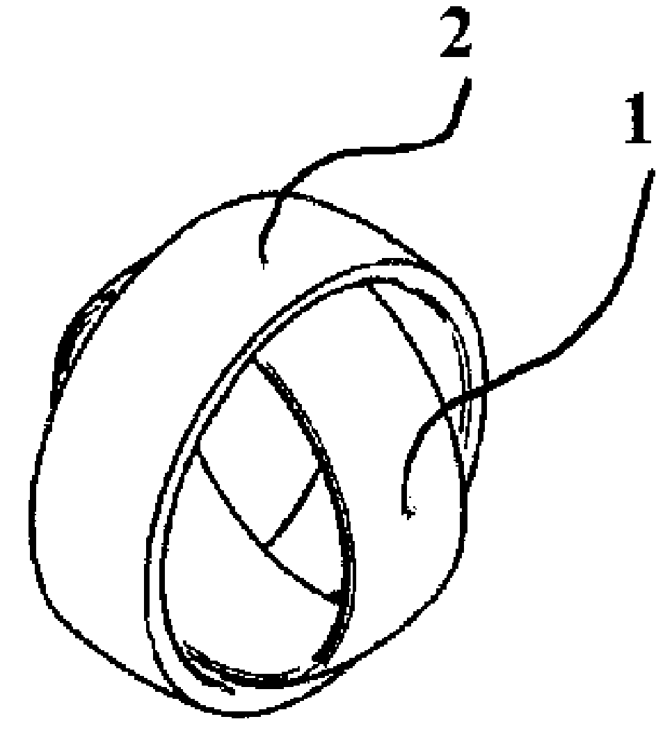
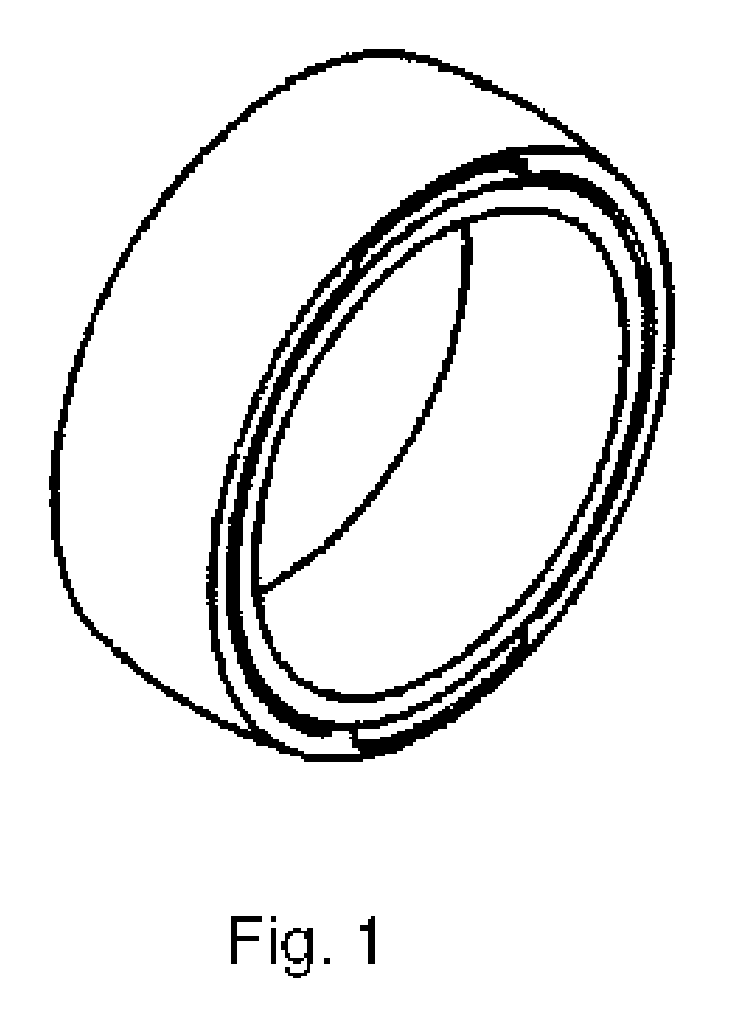
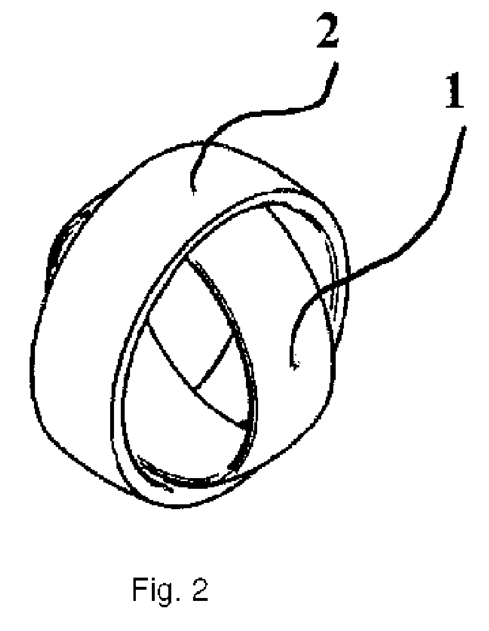
[0025]In FIGS. 1 through 8 a first sample model of an ornamental ring is represented in different views. The ornamental ring consists of an inner ring 1 and an outer ring 2. The outer ring has been provided with two indentations 7 on its inner side. Both indentations 7 are identically shaped and are positioned opposite each other, so that they have the greatest possible distance from each other on the inner side of outer ring 2. The angular distance in relation to the full circle of the outer ring is 180°. The inner side 5 of the outer ring 2 is curved outward. The outer side 6 of outer ring 2 is curved outward.

[0026]The profile of the inner side 3 of inner ring 1 has an inward curvature. This form facilitates putting the ring on and taking it off. The inner ring 1 can also be worn without outer ring 2. The outer side 4 of inner ring 1 has an outward curvature with a predetermined radius. This curvature is aligned to the curvature on the inner side 5 of outer ring 2 so that outer ri...


PUM


Abstract

An ornamental ring of at least two parts with an outer ring (2) as the first part, and an inner ring (1) rotatable around multiple axes against the outer ring as the second part. The inner ring is removable from the outer ring (2) without the use of tools and connectable to the outer ring without the use of tools, with an outward curvature on the inner side (5) of the outer ring (2), and a corresponding outward curvature on the outer side (4) of the inner ring (1). The inward facing surface of the outer ring (2), and the outward facing surface of the inner ring (1) are free of elements projecting above the surfaces, with two indentations (7, 8) positioned diametrically opposite on the inner side (5) of the outer ring (2). Both of these extend from one of the two edges of the outer ring to the area with the greatest internal diameter of the outer ring, with a distance between the indentations (7, 8) being greater than the external diameter of the inner ring (1) and with the width of the indentations (7, 8) being greater than the width of the inner ring (1).

Description

BACKGROUND OF THE INVENTION[0001]1. Field of the Invention[0002]The invention relates to an ornamental ring of at least two parts, with an outer and inner ring which are rotatable along multiple axes relative to each other.[0003]2. Description of Related Art[0004]Ornamental rings of this type are well known from a technological viewpoint, for example from DE 299 24 052 U1. The disadvantage with well-known ornamental rings is that the inner ring and the outer ring are connected together with axle stubs, ball bearings, bush bearings, or anti-friction bearings so that a simple removal of the inner ring from the outer ring is not possible. In particular, the person wearing the ornamental ring cannot remove the inner ring from the outer ring without using tools. This places limits on the configuration and flexibility of the ornamental ring.SUMMARY OF THE INVENTION[0005]It is an object of the invention to provide an ornamental ring containing an inner and outer ring, whereby the outer rin...

Claims


Application Information

Patent Timeline
IPC IPC(8): A44C9/00
CPCA44C9/003A44C9/0023
Inventor WUELFING, MATTHIAS
Owner WUELFING MATTHIAS
Learn More